Meshing the Model
The next step involves defining and generating a mesh for the manifold part and is carried out within the Mesh module in Abaqus.
- To switch to the Mesh module, expand the container and double-click Mesh (Empty).
The color of the manifold indicates which method Abaqus uses to mesh the part. Currently, most of the manifold is colored orange indicating that it cannot be meshed using the default element shape. Select a more appropriate element shape and use a free method to mesh the part:
-
Click
 (Assign Mesh Controls) in the mesh module toolbar or select
.
(Assign Mesh Controls) in the mesh module toolbar or select
.
- In the viewport, hold the <Shift> key and select the main part of the manifold and the partitioned outlet section. When both parts are selected, click Done.
-
In the
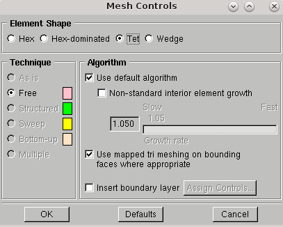
Mesh Controls dialog, change the
Element Shape to
Tet. Keep the default options and click
OK.
- Press Esc to exit the mesh controls tool.
Choose the element type for the manifold part. In this case, 4-node linear tetrahedral elements are used:
-
Click
 (Assign Element Type) or select
.
(Assign Element Type) or select
.
- In the same way as described previously, select both parts of the manifold in the viewport and click Done.
-
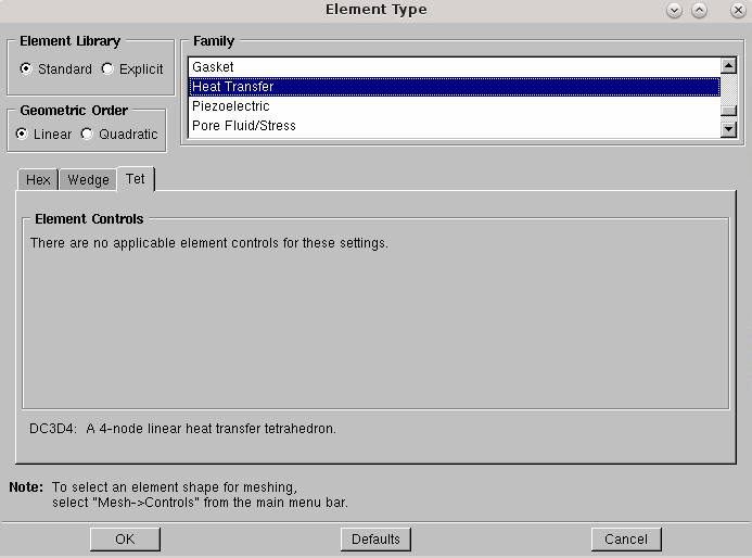
In the
Element Type dialog, set the following properties:
Property Setting Element Library Standard (default) Geometric Order Linear Family Heat Transfer The Tet tab is selected by default. The element selection DC3D4 is displayed at the bottom of the dialog.
-
Click
OK.
To determine the size of the mesh, specify a target global element size:
-
Click
 (Seed Part) or select
.
(Seed Part) or select
.
-
In the
Global Seeds dialog, set
Approximate global size to
0.005, then click
OK.
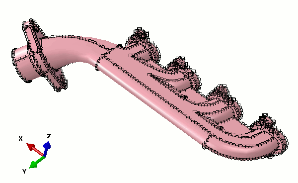
Seeds appear on each of the model edges.
-
Click
Done at the bottom of the viewport to confirm the assignment of these seeds to the part.
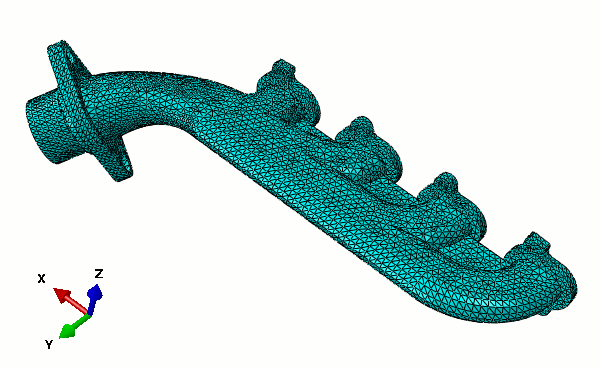
-
Generate the mesh by clicking
 (Mesh Part) or by selecting
. Click
Yes at the bottom of the viewport.
(Mesh Part) or by selecting
. Click
Yes at the bottom of the viewport.
- Save the model database by selecting .
- In the dialog that appears, navigate to the location to save the model, enter the name manifold, and click OK.