Defining Surfaces and Sets
Specify the FSI interface as the inner wetted surface of the manifold model, and define two additional surfaces to specify thermal conditions on the manifold exterior and the flanges.
To create a surface:
- Double-click Surfaces underneath the Assembly container in the Model Tree.
-
In the
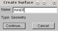
Create Surface dialog name the surface
INNER and click
Continue...
To select the inner faces of the model in the viewport:
- At the bottom of the window, set Select the regions for the surface option to by angle.
- Enter an angle of 89 and press <Enter>.
-
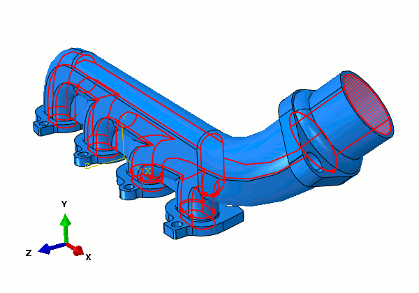
Hover the mouse pointer over one of the inner faces, and after a moment the inner surfaces are highlighted. Click to confirm this selection.
-
Once the inner faces have been highlighted, click
Done at the bottom of the viewport.
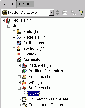
The surface is shown under the Surfaces container.
- Using the technique described above, create another surface called FLANGES.
-
In the viewport, rotate the manifold using
<Ctrl><Alt> and left-click. Hold the
<Shift> key and click the four flat faces on
the bottom of the inlet flanges.
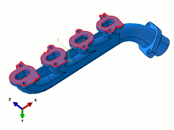
- Click Done at the bottom of the viewport.
- Finally, create a third surface called EXTERIOR.
-
In the viewport, use
<Shift>-click to select all the exterior faces on the manifold part, including any face on the model that was not part of the FLANGES or INNER surfaces.
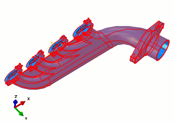
- Click Done to create the surface.
Next, define two geometry sets:
- Double-click Sets underneath the Assembly container.
- In the Create Set dialog, name the set INLET and click Continue.
-
Select the continuous set of edges around each inlet as shown below.
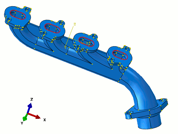
- Click Done when you have selected these edges.
The second set includes the entire model and is used to define the initial temperature across the manifold:
- Using the same technique as for the previous set, create another geometry set called ALL.
-
In the viewport, select the entire model by clicking in the space above and to the left of the model, and dragging the mouse down and to the right.
A box is drawn around the model, and everything within the box is selected when you release the mouse button.
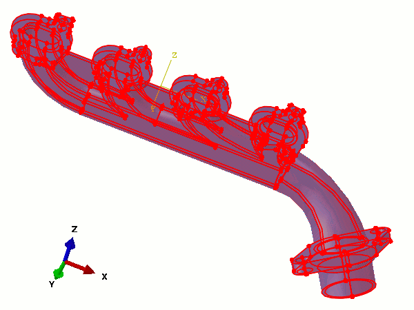
- Click Done to confirm the set.