Suppression of Wave Reflections at Boundaries
Wave Damping
Damping of waves is possible by introducing resistance to vertical motion. Simcenter STAR-CCM+ implements the method by Choi and Yoon [121], adding a resistance term to the equation for -velocity:
with:
where:
- is the starting point for wave damping (propagation in the x-direction)
- is the end point for wave damping (boundary)
- , and are parameters of the damping model
- is the vertical velocity component.
Wave Forcing
Following the approach of Kim and others ([128]), Simcenter STAR-CCM+ allows coupling of the 3D flow simulation with a theoretical solution that is specified by VOF waves.
Forcing the solution of the discretized Navier-Stokes equations towards another solution (such as a theoretical solution or simplified numerical solution) over a specified distance reduces the computing effort by using a reduced-size solution domain. This forcing also eliminates problems that are associated with reflections of surface waves at boundaries, owing to the damping feature of the gradual forcing.
Wave forcing applies only to Momentum. No Phase sources or Turbulence sources are added. Wave forcing is achieved by adding a source term to the transport (momentum) equations of the form:
where:
- is the forcing coefficient
- is the fluid density
- is the current solution of the transport equation
- is the value towards which the solution is forced.
When the solution needs to be fixed to a particular value of , a large number is used for . The remaining parts of the discretized equation then become negligible.
The source term from Eqn. (337) is applied with a variable forcing coefficient over a specified forcing zone. For example, the figure below is a schematic view of two overlapping solution domains. The 3D Navier-Stokes equations are solved in one domain, within the shaded zones. No forcing is applied within the inner zone (3D Navier-Stokes), but within the outer zone (Forcing zone) the forcing source term is activated along the solution domain boundaries. The width of the forcing zone can be different for different boundaries. The optimal width of the forcing zone depends on the problem that you are modeling.
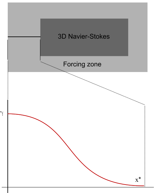
The forcing coefficient varies smoothly from zero at the inner edge of the forcing zone to the maximum value at the boundary (the outer edge of the forcing zone).
The volume coupling can also be either one-way or two-way, as the forcing zones usually do not coincide.