Generating the Mesh
Create the volume mesh for the graphics card components, the fans, and the air volume.
- Right-click the node and select .
- In the Edit dialog, set Name to Fans_SurfaceControl.
- Click the Surfaces text box, select the Inlet Fan and the Outlet Fan QuickParts, and click OK.
- For the Target Size, select Specify Custom Value from the drop-down menu and set the value to 20.0.
- Click Apply, then Close.
To generate the mesh:
-
Click
 (Generate Volume Mesh) in the
Mesh Generation toolbar.
The mesh generation process takes several seconds, depending on the specifications of your computer.
To visualize the mesh, hide the
default displayer and create a mesh displayer:
- Right-click the node and select Toggle Visibility.
- Right-click the node and select New Displayer.
- In the Edit dialog, set Name to Mesh.
- Click the Drawable Items text box and select all QuickParts.
- From the Display Mesh drop-down menu, select the Volume Mesh option.
- Click OK.
-
Click
 (Make Scene Transparent) in the
Visualization toolbar.
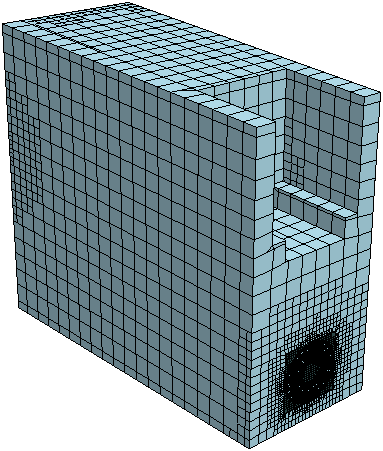
The mesh of the fluid domain is shown below.
To inspect the mesh on the graphics card:
- Right-click the node and select Edit Displayer.
- Click the Drawable Items text box and deselect Extract Volume, Inlet Fan, and Outlet Fan.
-
Click Apply, then Close.
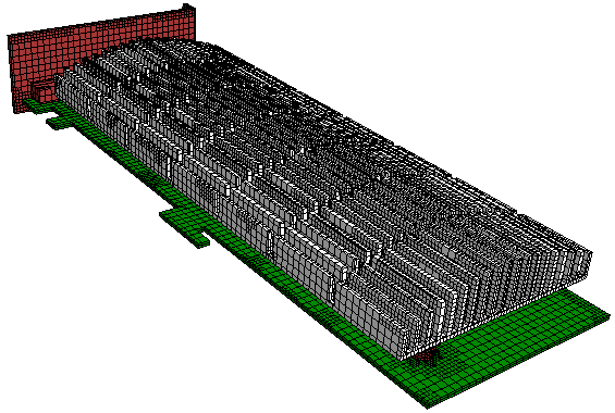
The following screenshot shows the mesh on the graphics card:

The mesh is relatively coarse. It is suitable for this tutorial to save computational expense. For an industrial analysis, a finer mesh would be required. -
Save the simulation
 .
.