Electrical Circuits
To simulate the response of a battery to an applied electrical load, you connect the battery and the load in an electrical circuit. When the simulation is run, the Circuit Solver computes the electrical solution for the circuit.
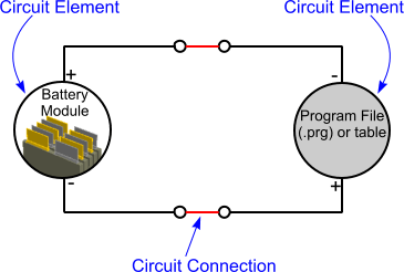
An electrical circuit is formed from elements and connections, as shown in the diagram below.

The internal structure of the battery module is illustrated below.

You can create multiple circuits and set the properties independently for each circuit. Using multiple circuits lets you simulate coupled circuits, such as in a transformer-type environment where the change in magnetic energy in one circuit is the voltage source for another circuit. You also use multiple circuits when you have multiple batteries in the same thermal environment, where each battery has its own load.
Besides current and voltage, the ecells within each battery cell maintain a state of charge parameter. The normal operating range for this parameter is from 0 through 1: a state of 0-percent charge (depletion of the cell) and a state of 100-percent charge (fully charged cell). When one or more ecells reach either of these limit values, the simulation can continue but the results can become unphysical.
The elements and connections for each circuit are stored in the corresponding node. For more information on how to define an electrical circuit, see Electric Circuits.