Battery Modeling in Simcenter STAR-CCM+
Battery modeling is the process of simulating the electrical and thermal response of a battery over the course of a load cycle. In Simcenter STAR-CCM+ Batteries, this process closely follows the physical structure of the battery, defined by either a stacked or spirally wound cylindrical assembly of the battery cell.
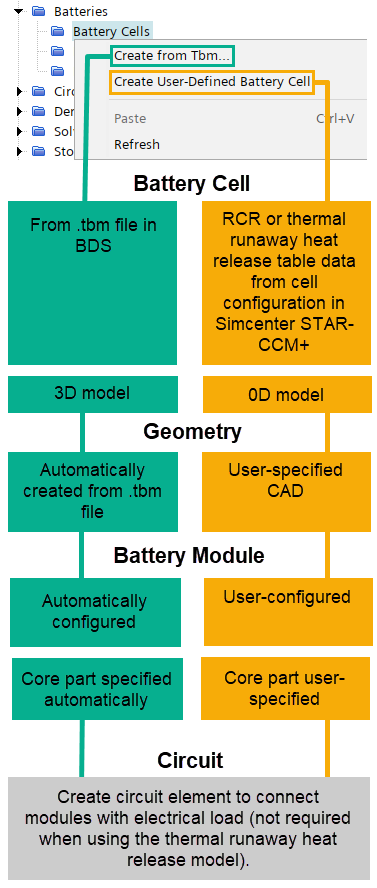
Simcenter STAR-CCM+ Batteries provides the option to simulate batteries which use either 3D battery cells or 0D battery cells. The following table outlines a comparison to help you decide which pathway is best with consideration to the information that you have and the output that you require.
| 0D Battery Cells | 3D Battery Cells |
|---|---|
|
|
Once the battery model is activated in Simcenter STAR-CCM+ Batteries, you can set up battery cells (spiral or cylindrical), battery modules, and electrical loads.
Battery Models
In addition to cell design, Simcenter STAR-CCM+ Batteries also incorporates the battery models and numerical algorithms of Simcenter Battery Design Studio. That is, most Simcenter Battery Design Studio models have been made a part of Simcenter STAR-CCM+ Batteries and can be used with a more detailed thermal model that is unique to Simcenter STAR-CCM+ Batteries.
Battery Cells
- A 0D cell is configured in Simcenter STAR-CCM+ using RCR Table data or the Thermal Runaway Heat Release model.
- A 3D cell is imported into Simcenter STAR-CCM+ Batteries as a .tbm file that is assembled in Simcenter Battery Design Studio—separate software for battery design and simulation. (See Simcenter Battery Design Studio).
- 0D Model
- The two different models that are available to configure a battery cell within Simcenter STAR-CCM+ are the RCR table model and the Thermal Runaway Heat Release model.
- RCR Table Model
- The RCR Table model requires you to provide the appropriate data for each given temperature in a table format. You can provide different data values for charge and discharge. For each given temperature, you can also provide data tables for specific values of maximum charge current and maximum discharge current.
- Thermal Runaway Heat Release Model
-
The Thermal Runaway Heat Release model predicts the heat that is released by the solid parts of the battery cell during thermal runaway. This model requires experimental data input, namely the heat rate in of the battery cell as a function of temperature of the battery cell. In Simcenter STAR-CCM+, this data is imported in the form of tables.
- 3D Model
- For the 3D model, a battery cell is imported as a .tbm file assembled in Simcenter Battery Design Studio.
- Stacked Cell
- For a 3D stacked cell,
the model only includes the stack and the tabs. In Simcenter STAR-CCM+, the collection of tabs from all
the positive electrodes in the cell is referred to as the positive tab
for the battery cell. Similarly, the collection of negative tabs from
all the negative electrodes is referred to as the negative tab for the
battery cell. The following screenshot shows an example of a single
battery cell in Simcenter STAR-CCM+.

- Cylindrical Spiral Cell
- For a 3D cylindrical
spiral cell, the model includes a jellyroll that is made up of a
positive and negative electrodes. The jellyroll is wound on a
cylindrical mandrel. Also imported are the negative and positive tabs, a
washer that joins all the tabs together, caps (internal posts) that
connect the washer to the actual posts, and a can and end plates that
enclose the cell. The following screenshot shows an example of a single
cell in Simcenter STAR-CCM+. The can is hidden to
show the interior parts.
- E-Cells
- E-cells define the structured electrical grid on a 3D battery cell and are used in Simcenter STAR-CCM+ to run the electrical solver portion of the battery modeling process. For 0D cells, the entire cell volume is modeled as a single e-cell. There is no internal electrical grid. For each e-cell, the electrical solver implements a one-dimensional battery model to compute voltage as a function of time, current, and temperature.
- For stacked cells, part
of the modeling strategy of Simcenter STAR-CCM+
is to allow you to decide the extent to which the discretization model
gets simplified in order to reduce computational expense. For instance,
in the following image an actual cell with one pair of positive and
negative electrodes is represented in Simcenter STAR-CCM+ in terms of e-cells on the x-y plane. In this
case, there is not any spatial variation of heat generation in the z
direction.

- For an actual cell with
more than one pair of positive and negative electrodes, the Simcenter STAR-CCM+ representation can again be
modeled as one e-cell in the z direction, meaning that the spatial
variation of heat generation is only on the x-y plane.
- Alternatively, this
actual cell can be modeled in Simcenter STAR-CCM+
as two, three or four cells in the z-direction. Using this modeling
strategy results in spatial variation of heat generation in the x, y and
z directions.

Geometry
Geometry and connector parts are created first when following the 3D battery cell method—or imported when following the 0D battery cell option, and then regions are created for the battery objects. A battery mesher is provided to mesh the battery objects—although, you can also use standard meshing operations in Simcenter STAR-CCM+. It is also possible to create a volume that automatically encases the battery, which can be used to define a fluid continuum around the battery.
Battery Modules
In Simcenter STAR-CCM+, sets of battery cells can be electrically connected in series or parallel to form a battery module. A simulation can contain several battery modules.
A set of cells that are connected in series is referred to as a string, and a set of cells that are connected in parallel is referred to as a unit.
- Series-First
- In a Series-First topology (the default), the strings of cells are connected in parallel. The number of cells that are connected in each string is N Series, and the number of strings that are connected in parallel within each module is N Parallel. The example below illustrates a series-first arrangement for a module with N Series = 3 and N Parallel = 2.
-
- Parallel-First
- In a Parallel-First topology, the units of cells are connected in series. The number of cells that are connected in each unit is N Parallel, and the number of units that are connected in series within each module is N Series. The example below illustrates a parallel-first arrangement for a module with N Series = 3 and N Parallel = 2.
-
The total number of cells in a module is the product of N Series and N Parallel. The circuit solver for each module makes electrical connections according to the values for N Series and N Parallel that you specify and the module topology that you select.
Connectors
The electrical connections between cells are not explicitly displayed in Simcenter STAR-CCM+. However it is possible to observe the connections after an electrical time step solution using the Tab Voltage field function. Each battery cell in a module has a positive and negative tab. The Tab Voltage function displays the circuit voltage that is computed at each tab that is displayed in a module.
You can add physical connectors between the cells of the battery modules. The main purpose of adding physical tab and terminal connections is to model the thermal solution more accurately. The physical connectors that you add must be consistent with the electrical connections that the circuit solver makes automatically. Within a string of cells, tab connectors join a positive or negative tab of one cell to the complementary tab of an adjoining cell. The open tabs at either end of the string of cells are referred to as terminals and these connections can be physically modeled using terminal connections. Both tab and terminal connections can be set up as illustrated below.
For spiral cells, a battery module looks as follows, showing two parallel units of cells that are connected in series.
In the above examples, alternate cells have been rotated in order to align the positive tab of one cell with the negative tab of its neighbor.
Solvers
Simcenter STAR-CCM+ Batteries uses a combination of an electrical solver and a fluid/thermal solver. The electrical solver calculates the electrical behavior of the battery cell while the fluid/thermal solver calculates the heat transfer within the cell and its surroundings.
- Electrical Solver
- The Simcenter STAR-CCM+ Batteries electrical solver calculates the electrical voltage and heat generation as well as, if applicable, chemical solution for each battery cell.
- Thermal Solver
- The Simcenter STAR-CCM+ Batteries thermal solver calculates the temperature field within the battery cell stack and throughout the rest of the thermal model and cooling system.
- Circuit Solver
- The circuit solver is used to connect battery modules to electrical loads from .prg files.
Circuits
See Electric Circuits.
To simulate batteries in Simcenter STAR-CCM+ Batteries, follow the Batteries General Workflow.