Inverse Die Method
It is possible to start with the desired cross section of an extrudate and calculate back to the shape of the die needed to produce it.
In the direct extrusion problem, the die surfaces are all stationary, but free stream surfaces must move in order to satisfy the dynamic and kinematic boundary conditions. In particular, the kinematic boundary condition on a free stream can be written as:
where is the velocity vector field and is the unit normal on the boundary. The above equation requires only one boundary condition along a line that crosses every velocity streamline. For direct extrusion, this condition would be imposed at the die lip. Alternatively, the boundary condition can be adopted at the end of the extrudate section (exit) and hence in this case the extrudate inlet (die lip) must be adapted. This can be achieved by allowing the die to be deformed.
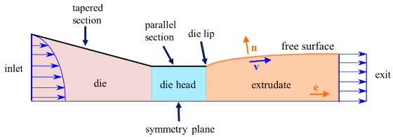
As shown in the figure above, this die adaptation is usually made in two parts: a linear section followed by a short parallel section. Both sections are particular cases of a linear adaptation in the extrusion direction .
A local principle from elementary differential geometry expresses the linearity in the extrusion direction :
where is the displacement vector. The variational form of the above equation is multiplied by the weight function and then integrated by parts. A stiffness coefficient is then introduced to give:
where denotes the Sobolev space consisting of square integrable functions for which the first derivatives are also square integrable, with the magnitude zero at the boundaries with essential (Dirichlet) boundary conditions. However, applying the above linearity requirement only in the normal direction (to the die boundary) yields:
The distinction between tapered and parallel sections is made by a distinction in the stiffness (greater value for the parallel section than for the tapered section).
Finally, note that the inverse die design can only be used in steady state condition.