Setting Boundary Conditions
Define the boundary types and specify the appropriate property values. The geometry that is used for this tutorial has six boundaries, three of which have no-slip wall conditions that are assigned to them. Of the remaining three boundaries, define two as pressure outlet boundaries and define the last one as a symmetry plane.
To set the boundary conditions:
- Rename the Default_Fluid 2D node to Fluid.
-
Edit the
node and set the boundary types as follows:
Boundary
Type
Bottom
Symmetry Plane
Left
Pressure Outlet
Middle
Wall
Right
Pressure Outlet
TopRight
Wall
TopLeft
Wall
The only boundary conditions that are specified are at the two pressure boundaries.
-
Edit the
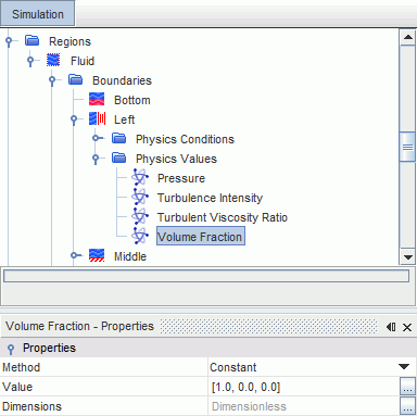
node and set the following properties:
Node Property Setting Pressure Value 5.0E7 Pa Volume Fraction Value [1.0, 0.0, 0.0] 
The Volume Fraction setting enforces the condition that only liquid water enters the solution domain through that boundary.
-
Edit the
node and set the following property:
Node Property Setting Volume Fraction Value [0.0, 1.0, 0.0] This setting enforces the condition that only air enters the solution domain through that boundary.
- Save the simulation.