Discrete Element Method
The discrete element method (DEM) is designed for modeling the granular flow of materials such as sand, food particles, powders, capsules, and slurries. These flows are characterized by a high particle density where the inter-particle interaction is of importance.
Established by Cundall and Strack [720], the DEM model extends the Lagrangian formulation to account for inter-particle interaction in the particle equations of motion. These forces cannot be ignored for highly loaded flows, that is, many interacting particles.
The DEM particles can assume different shapes and volumes. Simcenter STAR-CCM+ offers several options for simulating non-spherical particles (see DEM Particle Types) including using arbitrary convex or concave shapes defined by CAD geometry. The collision between non-spherical particles and other particles or walls can have more than one force-transmitting contact point.
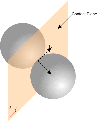
Simcenter STAR-CCM+ models DEM particles based on soft-particle formulation in which particles are allowed to develop an overlap. The calculated contact force is proportional to the overlap, as well as to the particle material and geometric properties. This contact force enters the Lagrangian momentum equation Eqn. (2958) as .

Discrete Element Method Particle Time Scale
To obtain the DEM particle trajectory, Eqn. (2958) is integrated over time using a characteristic DEM particle time scale.The particle time scale, and therefore the time-step, depends on one of three times associated with the particle:
- Rayleigh wave propagation time
- The maximum time-step that is allowed for a
DEM particle is constrained by the assumption that the force acting on a
particle is only affected by the particle’s immediate neighbors during a
single time-step duration. The time-step is therefore limited by the time it
takes the Rayleigh wave to propagate across the surface of the particle to
the opposite side [726] (from pole to pole in the case of a
sphere): (3244)
where is half the characteristic minimum dimension of the particle construed for its moment of inertia, (the radius in the case of a sphere).
The Rayleigh wave velocity depends on material properties, and the exact value is obtained as a solution to a secular equation [731]. Simcenter STAR-CCM+ uses an approximation of the solution that provides sufficient precision without incurring high computational cost [728], [729].
When the Linear Spring contact model is used,
(3245)where is the particle mass and is the spring stiffness.
The maximum time-step must be no more than , where is a user-defined time-scale.
- Impact duration
- The second time-step limiting criterion applied to moving particles is the
duration of impact of two perfectly elastic particles. For two identical
spheres of radius
, this duration, assuming the Hertz contact
theory, was derived by Timoshenko [735] to be: (3246)
The maximum time-step must be no more than .
- Particle transit time
- The final restriction on a DEM particle time-step is geometric. It is based
on the assumption that particles must not move too far within the time-step.
This condition prevents missing contacts between DEM particles, as well as
particles and walls. Therefore each particle is constrained such that it
takes at least 10 time-steps for the particle to move the full length of the
radius. (3247)
Artificial Viscosity
The artificial viscosity model is used to correct the results in cases where high impact velocities cause the numerical models to over-predict the overlap between the colliding objects. The energy that is dissipated by artificial viscosity represents unresolved processes of damage, deformation, and entropy.
The name "Artificial Viscosity" refers only to the similarity between the formulation of the Artificial Viscosity model and the formulations for viscosity. It does not refer to any physical effect resembling real viscosity.
This model introduces a force during compression (while the particles are overlapping and their centers are moving nearer) based on the von Neumann-Richtmyer artificial viscosity [738]:
where:
- is the artificial viscosity force.
- is the component of the velocity in the contact normal direction.
- is the equivalent (harmonic mean) mass of the particles.
- is the equivalent (harmonic mean) radius of the particles.
- is the speed of sound in the material. It is estimated from the equivalent mass and radius, and from the contact stiffness for the specific contact model in use.
- is the linear coefficient.
- is the quadratic coefficient.
The factor is a linear ramp function that is scaled to the particle sizes as:
where:
- is the penetration, the overlap distance between particles or between particle and wall.
- and are the upper and lower ramp limits. They are defined in terms of the ratio of the penetration to the equivalent particle radius .
This ramp function allows you to use artificial viscosity without affecting typical low penetration contacts.