Defining Boundary Surfaces
Before you convert geometry parts to regions, you are generally advised to identify and name part surfaces according to their final boundary conditions. You can split and combine part surfaces until you have the set of surfaces that best represent the boundary topology.
The following illustration shows the topology that you require when the model is transferred to a region with boundaries.
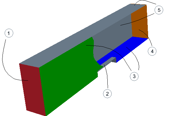
| Index | Description |
|---|---|
| 1 |
Stagnation Boundary |
| 2 |
Wall |
| 3 |
Symmetry Planes |
| 4 |
Pressure Boundary |
| 5 |
Slip Walls |
Initially, the whole imported surface belongs to one part surface. Using a split action from the geometry part context menu, you can pick underlying patches from the imported surface and form distinct part surfaces for boundary conditions.
To split the original surface and create named part surfaces:
- Expand the node.
-
Right-click the ColoredFace1 node and select
Split by Patch.
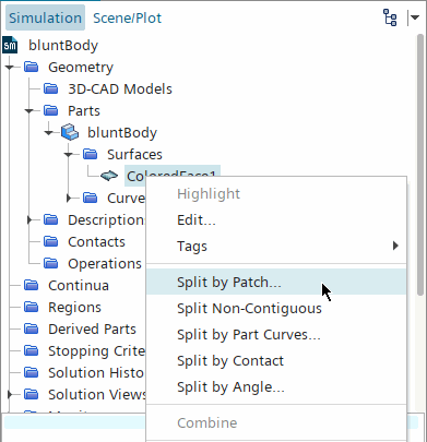
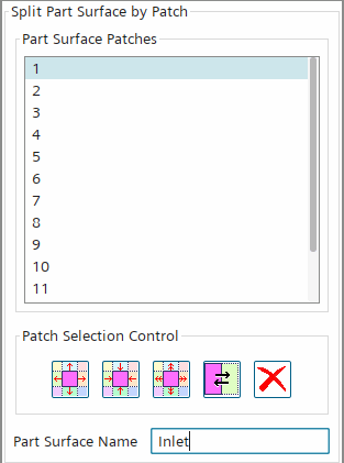
The Split Part Surface by Patch dialog appears. -
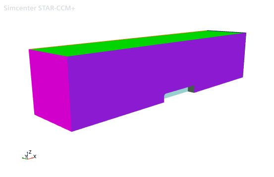
In Geometry Scene 1, select the face in the
low X direction by moving the mouse pointer over the face and clicking with the
left mouse button. To view the face, rotate the geometry as necessary. You can
determine the appropriate direction by observing the orientation of the triad in
the lower left corner of the scene. Each axis points from low to high.
-
Type
Inlet in the
Part Surface Name field.
-
Click
Create.
The face is removed from the scene and the new surface appears within the surfaces manager node belonging to the parent part.
-
Repeat the previous steps for the following surfaces:
Location
Corresponding part surface patch number
Name
High X face
3
Pressure
Low Z face
4
Symmetry_plane1
Low Y face
6
Symmetry_plane2
The outside walls of the region can be defined as a single boundary by combining two faces into one part surface using the multi-select functionality.
- Hold down the <Ctrl> key and click both the High Y and High Z faces.
- Type Slip_wall in the Part Surface Name.
-
Click
Create.
The remaining patches remain as part of the default surface.
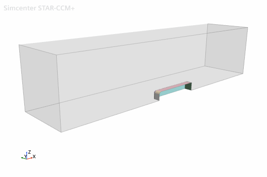
- Click Close.
-
To rename the part:
- Select the node.
- Press <F2>.
- Rename the part subdomain-1.
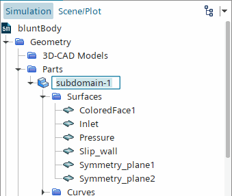
-
To rename the ColoredFace1 part surface—while you can
use the previous method—here you use the right-click menu:
- Right-click the node and select Rename....
- Rename the part surface, Inner_wall.
The parts are ready to be converted to a region and boundaries.