Dimension Types
A list of available dimensions, with a short description, is provided in the following table. For information on how to apply dimensions, see Dimensioning Sketches.
| Dimension | Description | |
|---|---|---|
|
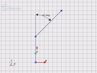
Angle |
An angle dimension
specifies the angle between two line sketch entities. The acute
angle is always displayed. If the angle between the lines is
obtuse, Simcenter STAR-CCM+ displays the
acute angle between one of the lines and an extension of the
other. The tolerance for an angle dimension is
0.001 radians, which is approximately
0.057 degrees.
 |
|
|
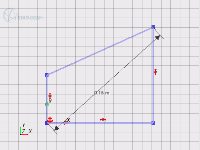
Distance |
A distance
dimension sets the straight-line distance between two selected
sketch entities. You can apply this dimension between a point
and a line, between two points, or between two lines.
 |
|
|
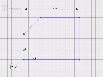
Horizontal Distance |
A horizontal
dimension sets the distance in the X-direction between two
points.
 |
To set an alignment for a line:
|
|
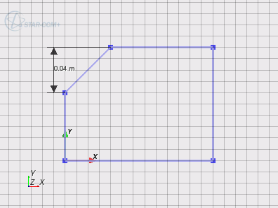
Vertical Distance |
A vertical
dimension sets the distance in the Y-direction between two
points.
 |
To set an alignment for a line:
|
|
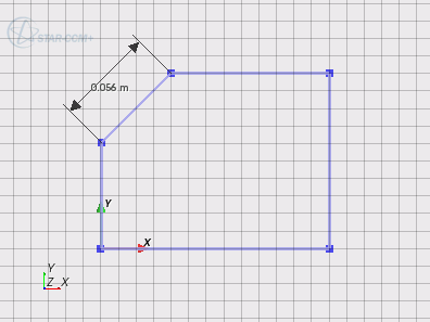
Length |
A length dimension
sets the length of a line sketch entity.
 |
|
|
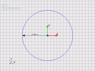
Radius |
A radius dimension
sets the radial size of a circle or circular arc sketch
entity.
 |
|
|
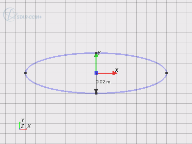
Minor Radius |
The minor radius
dimension sets the small diameter of an ellipse sketch
entity.
 |
|
|
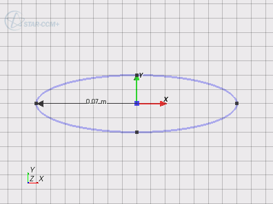
Major Radius |
The major radius
dimension sets large diameter of an ellipse sketch entity.
 |
|