Creating a Swept Feature
The Sweep and Sweep Cut features share the same procedure. To create a swept feature:
-
Select the sketch that contains the sweep profile.
In cases where you want to sweep multiple profiles, you can add more profile sketches using the Sweep panel.
-
Hold <Ctrl> and select the sketch that contains
the sweep path.
Note Steps one and two can be performed either by selecting the features in the feature tree or by selecting them in the 3D-CAD View window. -
Either:
- Right-click on either sketch in the
feature tree and select Sweep.
- Click
 (Sweep) in the 3D-CAD toolbar.
 - Right-click within the 3D-CAD View window and choose or Sweep Cut.
- Right-click on either sketch in the
feature tree and select Sweep.
- To add to the profile sketch selections, click within the Profile Sketches box, press <CTRL> and select further profiles in the graphics window.
-
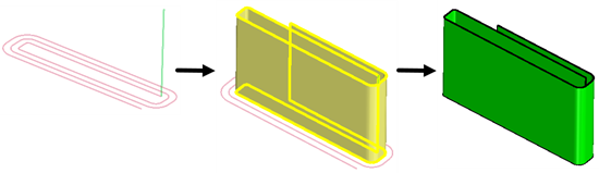
By default, the profile is swept along the entire length of the path. By
changing Direction Type to One Way or
Two Way, you can restrict the sweep to a certain
length only. For example, in the case of winding layers on a battery mandrel,
(which are necessary for ensuring prismatic cells), you can choose the
One Way option and extend the profile by a specific
length (Length 1).
- Enter the sweep parameters. See Sweep Panel.
-
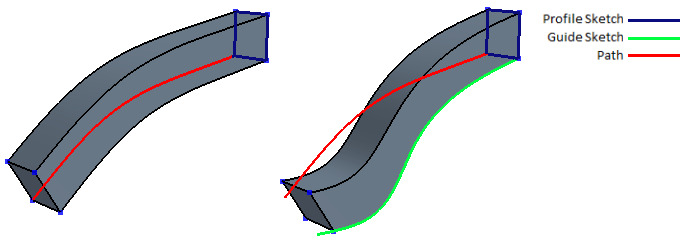
You can apply additional control over the shape of the sweep using
Guide Sketches. See Guide Sketches.
The image below shows a sweep with and without a guide sketch.
-
Expose any properties that you want as design parameters by clicking the
 (Expose Parameter) button next the desired feature.
- Click OK.