Configuring Energy Coupling Between Regions
For CHT simulations where the same timescale applies in both regions, you can use an implicit solution procedure that solves equations in both regions simultaneously. When the timescales differ, however, you must solve equations in each region consecutively. For this reason, an explicit mapped interface is required that can also provide time-averaged data to the solid side.
The energy coupling is achieved using an explicit mapped contact interface where the Boundary Heat Flux and by default the Specified Y+ Heat Transfer Coefficient at Y+ = 100 are exchanged across the interface. The fluid region sees the static temperature on the solid region, while the solid region receives convection data from the fluid side.
- Select the node and set Type to Mapped Contact Interface.
-
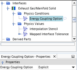
Select the node and set Energy Coupling
Option to Explicit.

-
Select the node and set Option to Instantaneous.
Instantaneous indicates that the thermal data from the solid side is mapped across the explicit interface to this boundary without being time-averaged. As the temperature of the solid changes at a much slower rate than that of the fluid, the instantaneous value is sufficient.
- Select the node and set the Option to Sliding Window Average.
-
Select the node and set the properties as follows:
Property Setting Sliding Sample Window Size 720 Sampling Delta Time ${FluidTimeStep(s)} Note This setting means that the rolling average is updated with a sample every 2 deg CA. With the Time Averaging Parameters defined above the boundary heat flux and heat transfer coefficient from the fluid side are averaged before being mapped across the explicit interface.
-
Select the node and set the following conditions:
Node Property Setting Physics Conditions  Thermal Specification
Condition Convection Physics Values  Ambient Temperature
Value 360 K  Heat Transfer Coefficient
Value 6.667 W/m^2-K - Save the simulation.