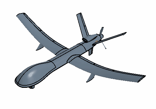
Stabilizer Freeform

To provide a planar surface for the stabilizer freeform, you first split the stabilizer body into two bodies using a plane. The planar surface allows Simcenter STAR-CCM+ to produce the correct linear behavior for the surface freeform operation. To perform the surface freeform, you place a freeform control point at the trailing edge wing tip. This results in a stabilizer with a higher sweep angle and a reduced angle of attack.

  1. To create a slicing plane:
    1. Right-click the Features > XY node and select Reference Geometry > Plane by Transformation.
    2. In the Plane By Transformation dialog, set the following properties:
      Property Setting
      Translation Vector [12.2, -0.82, 0.36] m
      Rotation Angle [45.0, 0.0, 0.0] deg
    3. Click OK.
  2. To slice the Left Stabilizer body:
    1. Right-click the Body Groups > Stabilizers > Left Stabilizer node, and select Boolean > Slice.
    2. In the Cutting Tools dialog, set Sketch Plane to Plane 1 and click OK.
      The stabilizer geometry follows the taper of the main body tail. The taper produces a non-planar surface between the main body and the stabilizer. To produce the required linear freefrom behavior, you create a planar surface at the stabilizer root.
  3. To freeform the stabilizer surface:
    1. In the 3D-CAD model tree, right-click the Body Groups > Stabilizers > Left Stabilizer node and select Show Only.
    2. In the 3D-CAD View 1 scene, select all faces except the base surface near the root of the stabilizer, as shown below:


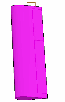
      Make sure to include all surfaces on the main stabilizer and control surfaces as well as the aerofoil tip face. Do not include the base surface near the root of the stabilizer.
    3. Right-click one of the selected faces and select Freeform Surface.
    4. In the Freeform Surface dialog, select (Create Point) and select the point on the trailing edge tip of the stabilizer as shown below:


    5. Select FreeFormPoint 1 and, in the Freeform Surface dialog, set Displacement to [1.5, 0.0, -1.0] m.
    6. Click Apply then OK.
      Simcenter STAR-CCM+ produces a linear deformation on the stabilizer. This linear deformation reduces the angle of attack of the stabilizer whilst increasing overall sweep of the airfoil. This decreases the drag of the stabilizer surface because of the change in sweep incidence along the airfoil.
    7. Right-click anywhere in the 3D-CAD View 1 scene and select Restore > Hidden Bodies.
  4. Right-click the Body Groups > Stabilizers > Right Stabilizer node and select Delete.
  5. In the Delete Bodies dialog, click OK.
  6. To mirror the Left Stabilizer onto the right-hand side of the aircraft:
    1. Multi-select the Left Stabilizer and Left Stabilizer 2 nodes.
    2. Right-click one of the selected nodes and select Transform > Mirror.
    3. In the Mirror Bodies dialog, set the following properties:
      Property Setting
      Normal [0.0, 1.0, 0.0] m,m,m
      Action Copy + Mirror Bodies
    4. Click OK.


  7. Group the five most recent features, as shown below:


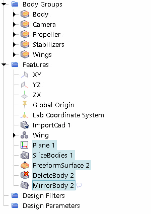
  8. Rename Features Group to Stabilizer.
  9. Save the simulation.