Wing Freeform
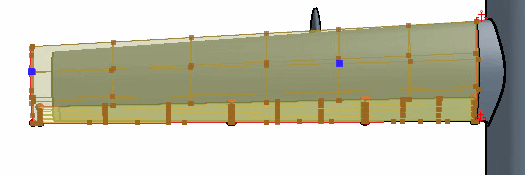
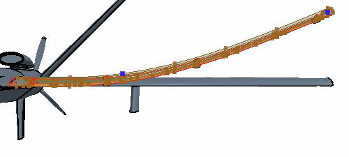
To control the deformation of the wing, you place two freeform points on the wing surface. These points are positioned at the wing tip (at the quarter chord location) and the upper surface of the wing (around two-thirds of semi-span location).
-
In the 3D-CAD View 1 scene, hold the Crtl key, double-click the main wing face and the
trailing edge face, and select the wing tip face.
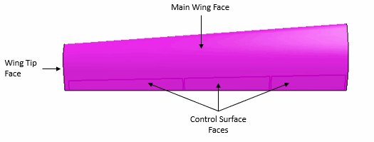
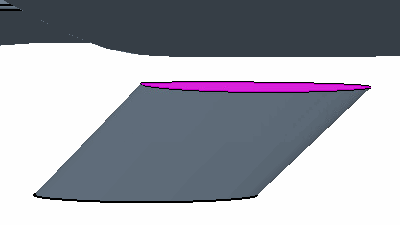
This selects all fifteen faces on the wing surface. When selecting the wing face, remember to include the main wing, the top and bottom surfaces of the control surfaces, all the faces along the trailing edge of the wing, and the wing tip face. Do not select the wing root face.
- Right-click one of the selected faces and select Freeform Surface.
-
To create the initial surface freeform:
An additional control point adds a rigid constraint to the
geometry. The constraint maintains the position of the geometry in the point
location when you make changes to the wing tip. The constraints force the surfaces
of the freeform through the control points.
To produce a smooth deformation, use a small number of control points. If you use too many control points, the surface can become over constrained, resulting in a wavy deformation and, in extreme cases, in the failure of the freeform operation.
-
To provide additional constraints to the deformation:
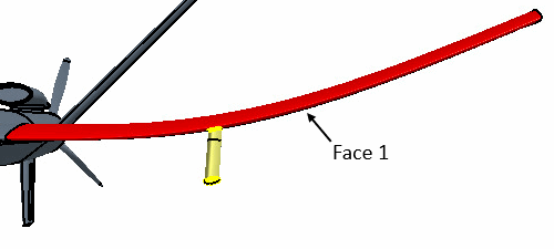
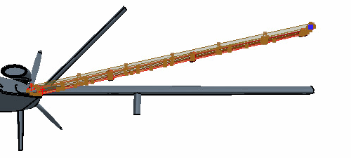
Due to the deformation of the wing surface, the hardpoint is no
longer attached to the wing surface. To reconnect the two bodies, translate the
hardpoint first, then extend the hardpoint body until the surface touches the wing
surface. If you perform the Extend Solid operation before the
translation of the hardpoint, the hardpoint body impinges on the wings trailing edge
control surfaces.
-
To change the position of the Left Hardpoint:
- Multi-select the and Right Wing Hardpoint nodes.
- Right-click one of the selected nodes and select Delete.
- In the Delete Bodies dialog, click OK.
-
To mirror the Left Wing and Left
Hardpoint onto the right-hand side of the aircraft:
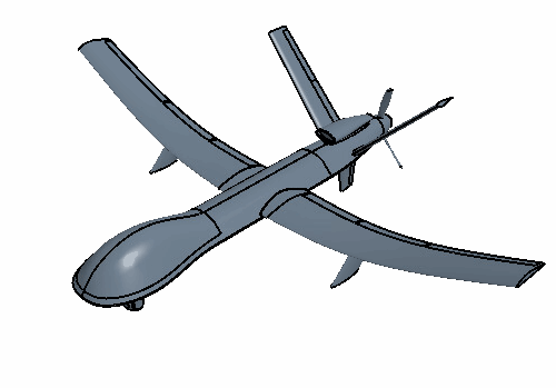
The mirror bodies operation maintains the line of symmetry down the center of the UAV, which ultimately maintains the physics behavior exhibited by the aircraft. The mirror bodies operation produces a copy of the source body reflects the geometry along the line of symmetry of the aircraft. If you make changes upstream of the mirror bodies operation to the source body these changes are reflected in the mirrored body when the pipeline is updated. -
Expand the Features node and multi-select the five most
recent features, as shown below:
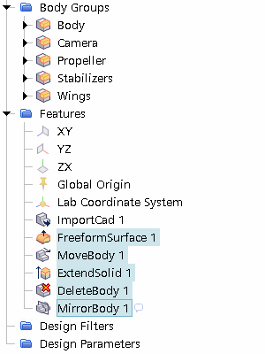
- Right-click one of the selected nodes and select Group.
- Rename Features Group to Wing.
- Save the simulation.
 (
(
 (
(
