Generating the Mesh
Create the volume mesh for the solid components and the fluid domain. For this tutorial, leave the overall mesh settings as default, but refine the mesh on the solder balls.
To define the mesh refinement on the solder balls:
- Right-click the node and select .
- In the Edit dialog, set Name to SolderBalls_SurfaceControl.
- Click the Surfaces text box, select the QuickPart, and click OK.
- For the Target Size, select Specify Custom Value from the drop-down menu.
- Activate Absolute Size and set the value to 2.0 mm
- Click Apply and Close.
To generate the mesh:
-
Click
 (Generate Volume Mesh) in the
Mesh Generation toolbar.
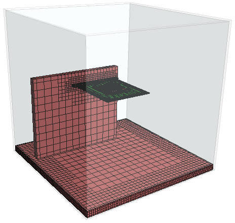
Upon completion of the mesh generation process, make the mesh visible on the test rig and the chip package:
- Right-click the node and select New Displayer.
- In the in-place dialog, set Name to Mesh.
- Click the Drawable Items text box and select all QuickParts except Chamber and Extract Volume.
- From the Display Mesh drop-down menu, select the Volume Mesh option.
- Click OK.
-
Position the parts to obtain a similar view to the one shown below.

-
Save the simulation
 .
.