Creating the Circuit
You use the circuit editor to create connections, which join the two modules in parallel, with a table that runs a World-wide harmonized Light duty Test Cycle (WLTC) on the battery pack.
-
Multi-select the following nodes, then right-click one of the nodes and select
Create Series Circuit
Elements:
-
In the Create Series Circuit Elements dialog:
- Set Start with to First Battery Module Negative Terminal.
- Click OK.
- Right-click the node and select .
-
Select the node and set the following properties:
Property Setting Table WLTC_Class3 Time Data Test Load Data Amps -
Right-click the node and select Open Circuit
Editor.
-
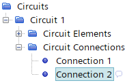
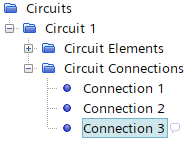
In the Circuit 1 window, complete the
following actions:
Action Result in Circuit Editor Result in Tree Connection 1 already connects the negative terminal of Battery Module 1 and the positive terminal of Battery Module 2. 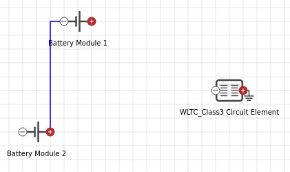

Click the  (Create Connection) icon,
then click the positive terminal of Battery Module
1, followed by the negative terminal of the
WLTC_Class3 Circuit Element. Press the
Enter key, then click
(Create Connection) icon,
then click the positive terminal of Battery Module
1, followed by the negative terminal of the
WLTC_Class3 Circuit Element. Press the
Enter key, then click
 (Save Changes).
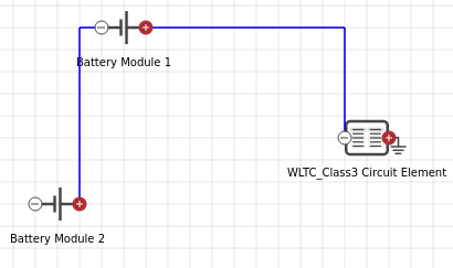
Click the
(Create Connection) icon,
then click the negative terminal of Battery Module
2, followed by the positive terminal of the
WLTC_Class3 Circuit Element. Press the
Enter key, then click
(Save Changes).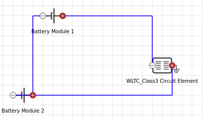
-
In the Circuit 1 window, complete the
following actions:
- Save the simulation.