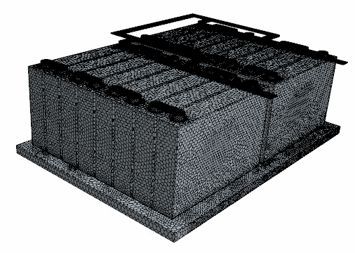
You generate a polyhedral mesh for the fluid and the solids with conformal
interfaces between them to compute the conjugate heat transfer. For the tabs and the
busbars, you use the Thin Mesher.
To generate the volume mesh and interfaces:-
Define an automated mesh operation to mesh the thin parts—the tabs and the
busbars:
-
Right-click the node and select .
-
In the Create Automated Mesh Operation
dialog, select the following parts: busbar1,
busbar In, busbar Out,
tab1, and tab2.
-
Select the Surface Remesher, the
Polyhedral Mesher, and the Thin
Mesher, then click OK.
-
Rename the Automated Mesh node as
Automated Mesh - Thin Parts.
-
Select the Automated Mesh - Thin Parts node and
activate Per-Part Meshing.
-
Select the node and deactivate Perform
Proximity Refinement.
-
Edit the Default Controls node and set the
following properties:
| Node |
Property |
Setting |
| Base Size |
Base
Size |
4 mm |
| Minimum Surface
Size |
Percentage of
base |
25.0 |
| Number of Thin
Layers |
Number of
Layers |
3 |
-
Define an automated mesh operation to mesh the battery cells:
-
Right-click the node and select .
-
In the Create Automated Mesh Operation
dialog, select the Cell part.
-
Select the Surface Remesher and the
Polyhedral Mesher, then click
OK.
-
Rename the Automated Mesh node as
Automated Mesh - Cell.
-
Select the Automated Mesh - Cell node and set
Mesher Execution
Mode to Parallel.
-
Select the node and set Base
Size to 4 mm.
-
Right-click the Custom Controls node and select .
-
Edit the Surface Control node and set the
following properties: .
| Node |
Property |
Setting |
| Surface Control |
Part
Surfaces |
bottom |
 |
Target Surface
Size |
Custom |
 |
Percentage of
Base |
50.0 |
-
Define an automated mesh operation to mesh the plate and the coolant:
-
Right-click the node and select .
-
In the Create Automated Mesh Operation
dialog, select the following parts: Coolant and
Plate.
-
Select the Surface Remesher, the
Polyhedral Mesher, and the Prism
Layer Mesher, then click
OK.
-
Rename the Automated Mesh node as
Automated Mesh - Cooling.
-
Select the Automated Mesh - Cooling node and set
Mesh Execution
Mode to Parallel.
-
Edit the Default Controls node and set the
following properties:
| Node |
Property |
Setting |
| Base Size |
Base
Size |
5 mm |
| Minimum Surface
Size |
Percentage of
base |
50.0 |
|
Size
Type |
Absolute |
| Absolute
Size |
0.5 mm |
-
Right-click the Custom Controls node and select .
-
Edit the Surface Control node and set the
following properties: .
| Node |
Property |
Setting |
| Surface Control |
Part
Surfaces |
|
 |
Prism
Layers |
Custom |
|
Customize Number of
Layers |
Activated |
|
Customize Total
Thickness |
Activated |
 |
Number of Prism
Layers |
1 |
 Prism Layer Total
Thickness Prism Layer Total
Thickness |
Size
Type |
Absolute |
|
Absolute
Size |
0.5 mm |
-
Define a mesh operation that patterns the volume mesh of the initial cell and
the tabs:
-
Right-click the node and select .
-
In the Create Volume Pattern Operation dialog,
click OK.
-
Select the Volume Mesh Pattern node and create
the following dynamic query for Input
Parts:
Name
contains
(
25 matching geometry parts consisting of all surface patterned
cells and tabs are found.
-
Click OK.
-
Create weak contacts between all solid battery components:
-
Right-click the node and select .
-
In the Create Contact Creator
Operation dialog, click OK.
-
Select the Contact Creator node and create the
following dynamic query for Input
Parts:
Name
does not contain
coolant
32 matching geometry parts consisting of all solid
parts are found.
-
Click OK.
-
Right-click the node and select Execute
All.
You can follow the mesh generation progress in the output window.
-
When the mesh generation process has finished, right-click the
Parts node and select .
Updating the interfaces results in the creation of the interface between
the battery cells and the plate.
-
Select the node and create the following dynamic query for
Contacts:
Type
is
Part Surface
Contact
Specifying the contacts in this form, as a dynamic query, ensures that the
contacts are assigned automatically in case the volume mesh is regenerated or
geometry parts change.
64 matching contacts are found.
-
Click OK.
-
To view the volume mesh, create a mesh scene.
-
Save the simulation.


