Electro-Deposition Coating
You can use the Electro-Deposition Coating model in Simcenter STAR-CCM+ to simulate e-coating and determine the paint layer thickness on a specified surface that is covered in a paint liquid.
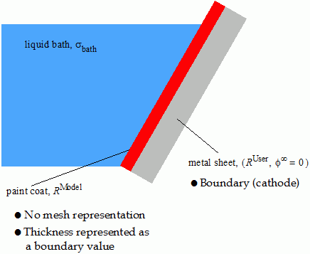
Calibration is required for a specific paint liquid along with given process parameters. The model can be combined with the VOF Multiphase model to cover gas bubbles resulting from dipping a body into a paint bath. The following figure illustrates the notation that is used in the model formulation.
The formulation makes the following assumptions:
- Simcenter STAR-CCM+ models the paint layer phase by a function that is available at a coated surface (boundary), rather than represented by a volume mesh.
- The formulation assumes a quasi-steady state for the electric potential. The steady equation is solved together with possible time-dependent boundary conditions.
- The model is calibrated against actual process parameters.
- The electric potential field and the layer growth do not affect the flow field.
- When using a differential equation to calculate the paint layer resistance, the following starting equation is found to be appropriate:(4179)
- When specifying the resistivity of the paint layer from which the paint layer resistance is calculated: (4180)
- When specifying the paint layer resistance directly:(4181)
Here is the paint layer thickness in . By default, the offset scalar profile is zero. The resistivity of the paint layer is and the overall resistance of the paint layer is .
The paint layer growth rate (paint deposition rate) is a function of the boundary-specific electric current at the interface between the paint bath and paint surface. The ODE (Ordinary Differential Equation) for paint layer thickness along a coated body boundary is:
where is calculated from the boundary conditions. The proportionality factor is the inverse of the electrochemical equivalent which is:
is the density of the paint solid in and is the solid paint coulomb efficiency in . is the minimum specific electric current ( ) which is required to observe any deposition at the boundary. The formulation assumes that the deposition rate is always positive or zero.
Measurements of polarization effects for different mixtures of paint indicate that there are further mechanisms to control the paint layer growth. Nonlinear functions are integrated and you can use the Minimum Accumulated Specific Surface Charge or Minimum Specific Current Squared Time Integral scalar profiles to control the contribution to thickness building. Values greater than 0 based on individual paint calibration affect the simulated paint layer thickness distribution.