Vorticity Confinement
Many areas of engineering today require tracking isolated vortices accurately over long distances.
Such areas include:
- Aerospace—vortices of aircraft wing-tips, helicopter blades, and other components
- Submarines—tip vortices of various control surfaces
- Wind turbines—tip vortices and their environmental impact.
An isolated vortex can be defined as the region in space with high values—and sometimes much higher values—of vorticity ( ), also referred to as vortex tubes. Tracking isolated vortices over long distances is important because of the induced velocity they produce. This velocity in turn influences the flow-field and aerodynamic processes—sometimes at great distances from the place where these strong isolated vortices have been produced.
Due to the built-in dissipation of state-of-the-art numerical schemes, any such simulation rapidly dissipates these vortices, unless a special treatment is applied. One such treatment is the vorticity confinement concept that John Steinhoff et al. introduced ([211], [194]). Others have refined this concept [193]. It is implemented in Simcenter STAR-CCM+ as the Vorticity Confinement Model.
The current implementation of the Vorticity Confinement model in Simcenter STAR-CCM+ is valid for both the Coupled Flow and Segregated Flow models in a low-speed flow regime ( ). The basic approach consists of adding a force term to momentum equations to help confine the vorticity and keep the vorticity from spreading. Vorticity confinement is a force per unit volume .
The force term is computed as:
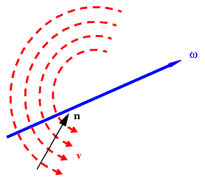
where , is fluid density and is the unit vector that is aligned with . The following diagram depicts the basic spatial relationship among and the vectors and .

where the model coefficient (non-dimensional) is set to 0.04 in three-dimensional cases and 0.02 in two-dimensional cases by default, and:
where is the local grid size, computed as:
is the non-dimensional wall distance:
where is wall distance, is kinematic viscosity of fluid, and is the mass average of velocity magnitude.
where is user-specified non-dimensional wall distance.
The factor effectively deactivates the vorticity confinement force next to solid walls (for example inside a boundary layer) for viscous (laminar and turbulent) simulations. Deactivating the model prevents the vorticity confinement force from affecting the boundary layer velocity distribution (and with it, factors such as skin friction). The model is deactivated next to the wall as suggested by the authors [211], [194], [193].
Both the non-dimensional cutoff wall distance and the model coefficient can be retuned for different simulation. Default values have been found to be appropriate for external aerodynamics.