Defining the Water and Air Phases
Create the water and air phases. Both phases use their default material properties.
To define the phases:
- In the Physics 1 continuum, right-click the node and create a new phase.
- Rename the Phase 1 node to Water.
-
For the Water phase, select the following models:
Group Box
Model
Enabled Models
Turbulent (Pre-selected)
Material
Liquid
Equation of State
Constant Density
- Click Close.
- Create a second phase and rename it to Air.
-
For the Air phase, select the following models:
Group Box
Model
Enabled Models
Turbulent (Pre-selected)
Material
Gas
Equation of State
Constant Density
- Click Close.
The VOF Waves model is used to model the interface between the water and air phases. This model is convenient as it provides an exact solution for the pressure field at the initial time-step.
-
Right-click and click .
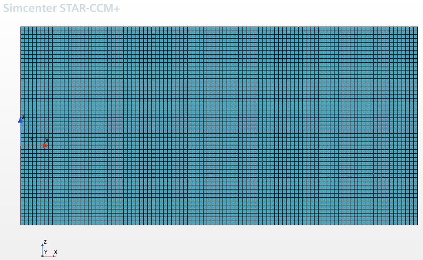
The Flat Vof Wave 1 node is added. The important property for this node is Point On Water Level, which specifies the initial position of the water surface. The default value is [0.0, 0.0, 0.0] m. The coordinate system for the initial mesh is arranged accordingly, with the zero point at the appropriate location for this simulation, as indicated below. Initially, the tank is filled with static water to near the half-way position.

The default property settings for the VOF Waves, Flat Vof Wave 1, and VOF Wave Zone Distance nodes are acceptable for this simulation.
-
Edit the node and set the following properties:
Node Property Setting Pressure Method Field Function Scalar Function Volume Fraction Method Composite N-1 
Method Field Function Scalar Function - Save the simulation.