Modeling Cold, Non-Thermal Plasma
Non-Local Thermal Equilibrium (non-LTE) plasma describes a type of plasma in which the electrons in the plasma have a greater thermal energy than the background gas. Despite the electrons having a high thermal energy, the overall temperature of the plasma corresponds with the temperature of the background gas—as the electrons are proportionally much smaller than the gas particles. Therefore, this type of plasma is known as cold, non-thermal plasma. In Simcenter STAR-CCM+, you can model cold non-thermal plasma using the Coupled Plasma Electron model.
-
For the fluid region in which you are modeling plasma, edit the
[physics continuum], make sure that
Auto-select recommended models is activated, and select the following models:
Group Box Model Space any Time Implicit Unsteady or Steady Material Gas or Multi-Component Gas Reaction Regime Non-Reacting Optional Models Plasma Enabled Models Coupled Plasma Electron Model (selected automatically) Electromagnetism (selected automatically) Gradients (selected automatically) Electrostatic Potential (selected automatically) Flow Coupled Flow Enabled Models Coupled Species (selected automatically) Coupled Energy (selected automatically) Equation of State Ideal Gas Viscous Regime Laminar -
Select any other optional models as required:
- To model ions within the plasma, also select the Electrochemistry model—the Electrochemical Species model is selected automatically.
- When dielectric surfaces are exposed to a flow of ions and/or electrons, an accumulation of charge can occur at the interface between the dielectric surfaces and the gas/plasma. If you intend to model an interfacing solid, to account for such charge accumulation, select the Charge Accumulation Model in the fluid continuum. See Charge Accumulation Model Reference.
- Select the node and set its Properties. See Coupled Plasma Electron Model Properties.
- Expand the node and specify values for the Mobility and Molecular Diffusivity of the electrons in the plasma. The Coupled Plasma Electron model solves transport equations using these values that you set.
-
Select the
Gas or
Multi-Component Gas node then:
- Specify the gas components of the background gas in the plasma. See: Managing Single-Component Materials or Managing Mixture Components.
- For each Gas Component, expand the node and set its Properties. Make sure that you specify the Elastic Electron Collisional Cross Section.
- If the Multi-Component Gas model is selected, you can also set for the combined gas components.
- Select the node and set Limiter Method to MinMod.
-
If the Electrochemical Species model is selected for modeling ions:
- Select the node and set its Properties. See Electrochemical Species Model Properties.
- To specify the electrochemical species components, right-click the node and choose Select Mixture Components or Import Species.
- When the electrochemical species components are selected, define the Material Properties for each electrochemical species component. See Electrochemical Species Component Properties.
-
For any solid regions which interface the gas/plasma, edit the
[physics continuum], make sure that
Auto-select recommended models is activated, and
select the following models:
Group Box Model Space any Material Solid Time Implicit Unsteady or Steady Optional Models Electromagnetism Electromagnetism Electrostatic Potential Select any other optional models as required:- To model charge accumulation at interfaces, for each solid continuum that interfaces the plasma continuum in which you are modeling a charge accumulation, select the Charge Accumulation Model.
-
To activate charge accumulation at an interface, make sure that the Charge
Accumulation Model is selected in the physics continua of the interfacing
gas/plasma and solid regions, then select the node and set Option to Active.
When an interface is set as a charge accumulation interface, all other conditions on that interface are removed and all associated boundaries to that interface are declared as charge accumulation interfaces.
-
Specify conditions and corresponding values for the following:
-
Specifically,
- Electron Number Density
For most cold, non-thermal plasmas, an appropriate value is between and
- Electron Temperature
For most cold, non-thermal plasmas, an appropriate value is between 0.3 - 2.0 eV
- Electron Number Density
-
Specifically,
- Electron Energy Density Source Option
Activate this property when you want to define the electron energy density source term, , which is used to calculate the collective electron energy density source term Eqn. (4193) for the energy density transport equation, Eqn. (4186).
- Electron Source Option
Activate this property when you want to define the electron source term, , which is used to determine the overall source term contributions for electron number density Eqn. (4192) in the number density transport equation, Eqn. (4184).
- Electron Energy Density Source Option
-
Specifically,
- Electron Number Density Specification
- Electron Thermal Specification
-
-
Set up any monitors, plots, and scenes that you require.
For example, you can monitor:
- Number Density of e-
- Electron temperature
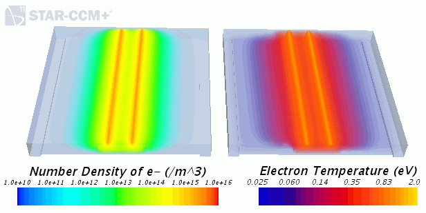
As a further example, the following scalar scene from Simcenter STAR-CCM+ shows the distribution of the, number density of electrons and electron temperature, within a process chamber for chemical vapour deposition at a pressure of 133Pa.
- Select the node and set the Maximum Steps.
- Run the Simulation.