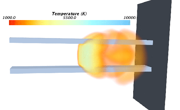
Modeling Plasma Arcs
When plasma is described as Local Chemical Equilibrium (LCE) plasma, the composition, temperature, and pressure of the background gas and plasma are equal. Since the electrons have the same thermal energy, composition, and pressure as the background gas, an equilibrium is assumed. Assuming an equilibrium where the properties of the gas are known allows you to use these tabulated material properties to define the plasma in Simcenter STAR-CCM+. Local Thermal Equilibrium (LTE) plasma describes a type of plasma in which the electrons in the plasma have the same thermal energy as the background gas.
-
For the fluid region in which you are modeling plasma, edit the
[physics continuum], make sure that
Auto-select recommended models is activated, and select the following models:
Group Box Model Space Axisymmetric, Three Dimensional, or Two Dimensional Time Any implicit Material - To model a single-component gas plasma, including air plasma with temperatures that are below 25,000K, select Gas.
- To model a multi-component gas plasma, select Multi-Component Gas.
- To model welding applications, select Multiphase.
Reaction Regime (when Multi-Component Gas is selected) Non-reacting Flow (when Gas or Multi-Component Gas is selected) Coupled Flow is appropriate for most plasma arc setups. If you selected Multi-Component Gas, the Coupled Species model is selected automatically.
Multiphase Model (when Multiphase is selected) Volume of Fluid (VOF) Multiphase Equation of State (selected automatically)
Segregated Flow (selected automatically)
Enabled Models Gradients (selected automatically) Equation of State (when Gas or Multi-Component Gas is selected) - If you selected
Gas:
- To model air plasma with temperatures that are below 25,000K, select Real Gas and then the Equilibrium Air model.
- For all other applications, select User Defined EOS.
- If you selected Multi-Component Gas, select User Defined EOS.
Optional Models Electromagnetism Electromagnetism Electrodynamic Potential Optional Models Magnetic Vector Potential Two-Way Coupled MHD Viscous Regime Any, although Turbulent is the most appropriate choice when modeling plasma arcs setups. Enabled Models Reynolds-Averaged Navier-Stokes (selected automatically) Reynolds-Averaged Turbulence Any, although K-Epsilon Turbulence is the most appropriate choice when modeling plasma arcs setups. Enabled Models Realizable K-Epsilon Two-Layer (selected automatically) Wall Distance (selected automatically) Two-Layer All y+ Wal Treatment (selected automatically) Optional Models Radiation Radiation Participating Media Radiation (DOM) Radiation Spectrum (Participating) Any Optional Models Ohmic Heating Quasi Unsteady Losses Note When the User Defined EOS model is selected, it is assumed that the plasma / gas is incompressible – and only dependant on temperature. This assumption is valid for flow speeds below Mach 0.7. For flow speeds above Mach 0.7, select the User Defined EOS model node and activate the Compressible property. Then populate the Material Properties with Temperature-Pressure dependant tables. See Using Table (T,P). - Select the node and set Limiter Method to MinMod.
-
If you are using the
Gas or
Multi-Component Gas model, select the
Gas or
Multi-Component Gas node then:
- If you are using the Multiphase model, set up the phases and define any phase interactions. See Defining Eulerian Phases and Defining Phase Interactions.
-
To avoid destabilization, you can either:
- initialize the plasma arc using a temperature that is large enough to result in a sufficiently large electrical conductivity (1 S/m - 100 S/m), or,
- set an artificial conductivity by specifying a minimum value for the Electrical Conductivity Constraint Option.
-
Specify conditions and corresponding values for the following:
-
Expand the
Solvers node and check that the Properties for each solver are appropriate for the application that you are modeling. Use the following values as a guideline for modeling most types of plasma arc simulations:
If you use the Coupled Flow solver, you can also use the expert driver to further improve the stability of the simulation.
Node Property Value [Coupled Flow] Courant Number 0.5 – 2.0 Electric Potential Under-Relaxation Factor 0.3 – 0.9 Magnetic Vector Potential Under-Relaxation Factor 0.4 -
Set up any monitors, plots, and scenes that you require.
For example, you can monitor:
- Temperature
- Velocity

- Select the node and set the Maximum Steps.
-
To improve convergence, you can adjust the time-step size and the number of inner iterations to suit the application that you are modeling.
- Select the node and set the Time-Step. Increase the value for non-compressible flows and decrease the value for supersonic flows.
- Select the node and set the Maximum Inner Iterations. For unsteady simulations, increase the Maximum Inner Iterations to a value that is between 24-96.
- Run the Simulation.
