Expanding the Cylinder
The same exercise can be repeated to model an expansion of the cylinder instead of a contraction. A displacement is specified at the wall boundary instead of a grid velocity.
- Select and save the simulation with a filename of expansion.sim.
-
Create a field function for the cylinder wall displacement with respect to the local cylindrical coordinate system:
The morpher conditions on the cylinder wall must be modified to use the new field function.
-
Edit the
node and set the following properties:
Node Property Setting Physics Conditions  Morpher Specification
Specification Displacement  Morpher Displacement Specification
Specification Coordinate Offset Physics Values  Coordinate Offset
Method Field Function Vector Function Cylinder Wall Displacement Coordinate System Laboratory->Cylindrical 1
This completes the changes necessary for the expansion simulation.
- Select from the menu bar and click OK.
-
Proceed to initialize and run the simulation as before using either the
option or the
 (Run) button on the toolbar.
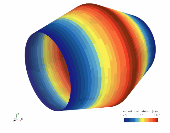
At the end of this second simulation:
- Click the Cylinder Wall tab at the top of the Graphics window.
-
Use the mouse buttons to zoom out and position the part to obtain a view similar to that shown below.
