Visualizing the Solution
View the velocity vector field as the solution develops on a plane bisecting the fluid and porous regions.
Start by creating a vector scene:
-
Right-click the node and then select .
The Vector Scene 1 display appears.
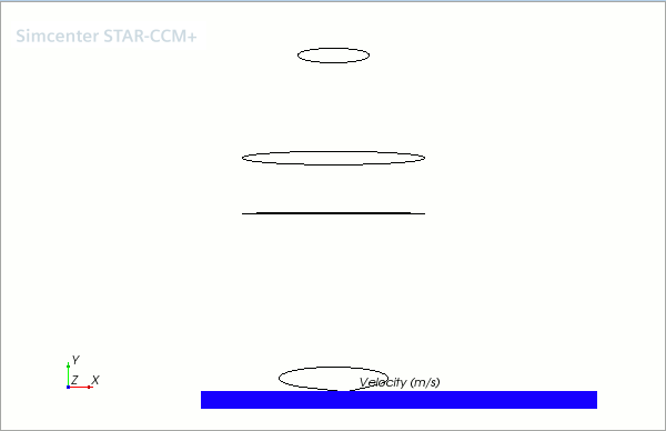
There are currently no parts in Vector Scene 1. You therefore need to create a plane section to display the vectors on.
-
Right-click the node and select .
The Create Section dialog appears in the edit tab of the simulation window.
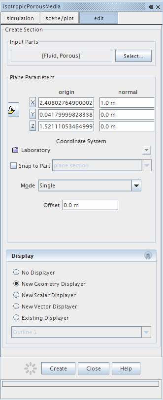
-
Click
Select...
to open the
plane section dialog. Make sure that the
and
regions (without their boundaries) are selected.
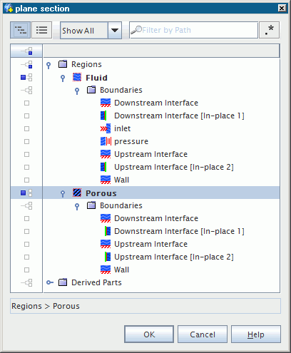
- Click OK.
-
In the
Plane Parameters box, make sure that the normal vector is set to [1,
0,
0].
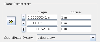
-
In the
Display box, select
.
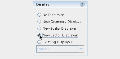
- Click Create and then Close.
-
Click the
 button at the top of the
Vector Scene 1 window and select
.
The section is now clearly visible as part of the display.
There are currently two vector displayers included in the plot. To remove the unnecessary one:
-
Open the node, right-click the node and select .

- Click Yes in the Confirm Object Deletion dialog.
- Select the node and click the right half of the Parts property.
-
In the dialog that appears, click the
 column selection button twice to clear all selections.
-
Select the
node.
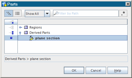
-
Click
OK.
The vector scene is now ready.
- Save the simulation.