Reacting Channels Workflow
The Reacting Channel co-simulation model in Simcenter STAR-CCM+ allows you to exchange data between reacting channels that use a one-dimensional Plug Flow Reactor (PFR) and three-dimensional Simcenter STAR-CCM+ simulations.
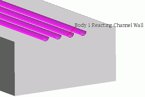
- you have a fluid domain with a three-dimensional mesh that contains unmeshed voids that represent the reacting channels.
- the Steady model is previously selected.
| Note | For an example of how to use the Reacting Channel Co-Simulation model, see the Reacting Channels: Steam Methane Reforming tutorial. The tutorial demonstrates how you set up firebox and the physics for the reacting channels. |
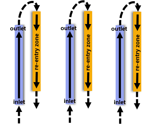
When using the reacting channel coupling model, set up at least one reacting channel co-simulation zone. Each reacting channel zone can represent several geometrical channels. At least two zones are required when simulating a reacting flow which exits channels in one zone (a Specified Inlet zone) and re-enters channels in another zone (a Re-Entry zone).

-
For the physics continuum that represents the fluid domain that surrounds the reacting channels, select the following models—in addition to the models that are previously selected, with
Auto-Select recommended models activated:
Group Box Model Reacting Flow Models (when the Reacting model is selected) - Flamelet
Often the most appropriate for firebox combustors.
- Reacting Species Transport
For detailed reaction mechanisms.
Flamelet Models (when the Flamelet model is selected) Any
For example, Flamelet Generated Manifold (FGM) is suitable for all premixed or partially premixed flames where the flamelet assumption is valid.
Further model selections are necessary.
Reacting Species Models (when the Reacting Species Transport model is selected) Any
For example, Complex Chemistry is applicable for combustors with multiple fuel streams, and with kinetically dominant processes such as flame quenching.
Further model selections are necessary.
Optional Models Co-Simulation Co-Simulation Models Reacting Channel Reacting Channel Coupling Models Reacting Channel Steady Coupling (selected automatically) - Flamelet
-
Click
Close.
Simcenter STAR-CCM+ adds the External Links node and a single Reacting Channel Co-Simulation sub-node.
-
Create a Reacting Channel Co-Simulation node for each
reacting channel mechanism that you want to use. To specify more than one
reacting channel mechanism, right-click the External
Links node and select .
A Link node appears, which you can set up as another reacting channel co-simulation.
- Select the node and specify the parameters that are required for coupling.
- Right-click the node and select Import Chemistry Definition (Chemkin format).
- In the Import Chemkin Files dialog, browse to and select the appropriate files, then click OK. When you intend to use user coding, you select an edited Chemkin file for the Fluid Chemistry Reaction File which contains a list of atoms and species only.
-
Select the node and set Method to either:
- To use internally-defined reaction types in the standard Chemkin format, select Internal (default).
- To specify reactions with user coding, select User-Defined.
-
To import and set up the user coding:
-
To create more reacting channel zones, right-click the
node and select
New.
A Zone [2] node appears.
-
To specify the boundaries for a reacting channel zone, group the boundaries for each reacting channel zone.
- Right-click the node and select New Group.
- Rename the New Group node appropriately.
- Expand the Boundaries node and multi-select the boundaries for one reacting channel zone.
- Drag the selected boundaries on to the [New Group] node.
You can use the [New Group] node to edit the Properties, Conditions, and Values of all boundaries that it contains.
- Right-click the [New Group] node and select Edit.
- In the Multiple Objects dialog, expand the node and set External Code Coupling Specification to the Reacting Channel Co-Simulation Zone for the selected boundaries.
- Group the remaining boundaries as necessary, and select an appropriate zone for the External Code Coupling Specification for each group of boundaries.
-
Specify the Conditions and Values for each Zone within each Reacting Channel Co-Simulation.

In particular, specify the following conditions and values:
- Set the parameters of any other , as required.
-
For the continuum that represents the fluid domain which surrounds the reacting channels, define any necessary parameters for the
Reference Values and
Initial Conditons.
Make sure that you specify the initial Species Mass Fraction.
-
Define any necessary Physics Conditions and Values for the Region and Boundaries.
- For the inlet boundaries, specify the Species Mass Fraction and the Mass Flow Rate.
- For the wall boundaries within the reacting flow region, specify the Surface Emissivity.
- Return to the Reacting Flow General Workflow.


