Reacting Flow General Workflow
Simcenter STAR-CCM+ supports several types of combustion analysis, each with their own workflow. Use this section to help identify the choice of models that are appropriate for the type of analyses you intend.
Import or create geometry parts that represent the volume in which the reacting flow occurs. You can use Simcenter STAR-CCM+ in serial or parallel mode.
Before selecting physics models and setting up physics parameters, it is important to have appropriate geometry and a suitably refined mesh in Simcenter STAR-CCM+. The detailed workflow that you follow depends on the physics of the application that you intend to simulate. Simcenter STAR-CCM+ provides a wide range of physics models that you can use in different combinations to suit different types of reacting flow processes. Follow the advice that is given in the introductory pages of the Reacting Flow section to help you determine which specific detailed workflow to use in addition to this workflow.
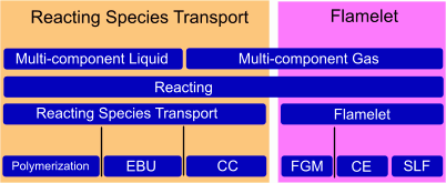
The following diagram provides an overview of the initial physics models that are required in the two most common detailed reacting flow workflows.

-
Generate a quality mesh to represent the reacting flow volume.
A polyhedral mesh is suitable for modeling most combustion applications as polyhedral cells generally have a low skewness and can calculate a more accurate face flux than tetrahedral cells. Polyhedral cells also provide a smooth volumetric growth, which is important for capturing complex geometry effectively.
It is important to consider refining the mesh by increasing the resolution in significant areas or volumes of the geometry. For example:- Refine mesh on and around fuel jets.
- Create a higher resolution mesh in narrow volumes.
- Refine mesh on impellers and baffles.
- In simple geometries, where mixing occurs, use volumetric refinement.
- In complex geometries, where mixing occurs, use solution based refinement.
- When modeling combustion
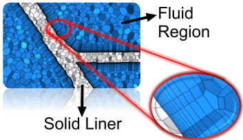
with conjugate heat transfer, create a conformal mesh at the
interface. It is also necessary to capture the boundary layers by
using the Prism Layer mesher to create orthogonal prismatic cells
next to the walls.

-
Decide which detailed workflow is most suitable for the application that you are modeling.
It is useful to consider how and where the reactions are happening in the application that you are simulating, as these details help to elicit the most appropriate workflow.
-
Before following the steps within one of the specific detailed workflows, for the physics continuum that represents the reacting flow volume, start to select appropriate general physics models:
Group Box Model Material -
For Flamelet workflows, select Multi-Component Gas.
-
For Reacting Species Transport workflows, select Multi-Component Gas or Multi-Component Liquid.
- For Reacting Channels workflows, you select the type of material that best represents the fluid domain that surrounds the reacting channels (not the material within the reacting channels).
- Multi-Component Gas
- Multi-Component Liquid
- Liquid
- Gas
-
For Lagrangian Multiphase, interphase workflows, select the material type that surrounds the reacting particles—not the material of the reacting particles:
- Multi-Component Gas
- Multi-Component Liquid
- Liquid
- Gas
-
For Eulerian Multiphase, interphase or intraphase workflows, select Multiphase.
- For Fluid Film, interphase workflows, select Multi-Component Gas.
-
For Polymerization workflows in which polymerization occurs within:
- a multi-component liquid (non-multiphase), select Multi-Component Liquid.
- a multi-component liquid phase in a multiphase polymerization setup (such as in a fluidized bed reactor or stirred tank reactor), select Multiphase.
-
For Surface Chemistry workflows, select Multi-Component Gas or Multi-Component Liquid.
Space - Axisymmetric
- Three Dimensional (required for Adaptive Mesh Refinement)
- Two Dimensional
Time - Implicit Unsteady (required for Lagrangian Multiphase Interphase workflows).
- PISO Unsteady (Segregated Flow Only)
- Steady (required for Reacting Channels and Reactor Network workflows)
When any Unsteady model is selected with a Flamelet reacting flow model, the Ideal Gas is compressible, and when Steady is selected, the Ideal Gas is incompressible.
Optional Models If required, select Adaptive Mesh to improve the volume mesh's ability to resolve the internal flame structure by refining or coarsening cells based on adaptive mesh criteria as they query the flow solution. See Adaptive Mesh Refinement. Reaction Regime (for Multi-Component Gas or Multi-Component Liquid) -
For the Flamelet and Reacting Species Transport (including Polymerization) workflows, select Reacting.
- For Fluid Film, interphase workflows, if reactions occur in the neighbouring gas phase, select Reacting, otherwise select Non-Reacting.
- For the Reacting Channels workflow, if reactions occur in the fluid that surrounds the reacting channels, select Reacting, otherwise, select Non-Reacting.
-
For the Lagrangian Multiphase, interphase workflow or the Multiphase Volume of Fluid (VOF) intraphase workflow, select Non-Reacting. The reactions are defined in the phase.
-
For the Surface Chemistry workflow:
- If the fluid mixture is only undergoing surface reactions and there are no other reactions, select Non-Reacting.
- If reactions are occurring within the volume of the fluid mixture in addition to the surface reactions, select Reacting.
Multiphase Model (for Multiphase)
For Eulerian Multiphase, interphase or intraphase workflows, select one of: - Eulerian Multiphase (EMP)
- Mixture Multiphase (MMP)
- Volume of Fluid (VOF). Required when using a flamelet model for intraphase reactions.
-
-
Proceed to the specific reacting flow workflow that you have decided to follow—keeping in mind any specific models that you think are appropriate for the application that you are simulating.
- Reacting Species Transport Workflow (also for intraphase reactions)
- Polymerization Workflow (for polymerization in a non-multiphase multi-component liquid)
- Flamelet Workflow (also for intraphase reactions with VOF Multiphase)
- Interphase Reactions Workflow: Lagrangian Multiphase
- Interphase Reactions Workflow: Multiphase (for multiphase polymerization)
- Interphase Reactions Workflow: Fluid Film
- Surface Chemistry Workflow
- Reacting Channels Workflow
- Reactor Network Workflow
- For the continuum, define any necessary parameters for the Reference Values and Initial Conditions.
-
If the Adaptive Mesh model is selected, specify the
adaptive mesh refinement criteria.
-
Define any necessary Physics Conditions and Values for the Region and Boundaries.
For example:
- For a wall boundary, you can define any flux at the boundary using the boundary physics condition, Wall Combustion Scalar Option.
- For regions in which reacting flows are affected by a momentum source such as a fan, you can define the momentum source using the region physics condition, Momentum Source Option.
- If you are modeling the Fuel NOx for a purely gaseous fuel, it is important to specify values for the inlet composition which include the intermediate species, HCN and/or NH3.
Note It is possible to specify several combustion model constants as parameters. See Global Parameters. -
Specify the required Solver settings and Stopping Criteria.
Note Make sure that the Under-Relaxation Factor property for the energy and species solvers are both set to the same values. -
Set up any Reports, Monitors, Plots, and Scenes that are required for Post-Processing.
For example:
- To determine if a reacting flow simulation solution is converging, you can generate a heat balance plot from a report.
- Right-click the Reports node and select .
- Select the Heat Transfer 1 node and set Parts to all of the inlet and outlet boundaries for the reacting flow region.
- Right-click the node and select Create Monitor and Plot from Report.
- Open the
.
When you run the simulation and the plot settles at a value that is close to zero, this shows that the heat at the inlet and outlet boundaries is reconciled and the solution has converged.
- To plot a specific field function within the reacting flow region, or at a boundary, you can generate an XY Plot. For example, you can monitor the temperature on the surface of reacting channels, the mass fraction of CO emissions at an outlet, or the progress variable within a reacting flow region. For more information, see
Plotting Results.
- Right-click the Plots node and select
- Expand the
node and set at least the following parameters:
Node Property Setting XY Plot 1 Parts Select the region or boundary on which you want to monitor the chosen field function.  Y Types
Field Function Select a field function that you want to monitor.
- You can visualize physics values on or within the reacting flow geometry using scalar scenes and vector scenes. For Example, you can visualize the flame area density within a scalar scene, or the velocity of the reacting flow within a vector scene. For more information, see Scenes.
- To determine if a reacting flow simulation solution is converging, you can generate a heat balance plot from a report.
- Save the simulation.
-
Run the simulation.
Simcenter STAR-CCM+ provides the Acoustic Modal Analysis post-processing model which uses an n-tau model to model the effect of the unsteady heat release rate on the acoustic pressure. The Acoustic Modal Analysis model allows you to simulate acoustic mode shapes, frequencies, and linear growth rates. You perform acoustic modal analysis from a previously converged solution. For further details see: Acoustic Modal Analysis.
Troubleshooting
- Initialising an Unsteady Calculation Through a Steady Calculation
-
Steady calculations converge best with the incompressible option activated, while unsteady calculations converge best with the incompressible option deactivated. When initialising an unsteady calculation through a steady calculation, the following workflow is advised:
- Converge the steady calculation with the incompressible option activated (default option when the Steady model is used with a Flamelet model).
- Deactivate the incompressible option and re-converge.
- Switch to using the Unsteady model—keep the incompressible option deactivated.
- Temperature Out Of Bound
- When the temperature is out of bounds, a message similar to the following is displayed: Temperature limited to [maximum/minimum] value [n] times on model-part "[part]"
- Heat Loss Ratio Out Of Bound
- When the heat loss ratio (HLR) is out of bounds, a message similar to the following is displayed: Heat loss ratio limited to [maximum/minimum] value [n] times on model-part "[part]". If this message only appears at the start of a computation, or only occasionally throughout the computation, take no action.
