Setting Up the Injector
Define the injector that is used to introduce the particles into the solution domain.
The particles of the dispersed Lagrangian phase are introduced into the solution domain using an injector. The injector defines the initial state of the particles and their spatial distribution. In this tutorial, introduce particles near the inlet with a velocity matching that of the continuous phase.
A new derived part based on a presentation grid is created to define the injection points, as this improves the distribution of particles across the pipe section.
To set up the injector:
- Right-click the Derived Parts node and select
- In the Create Presentation Grid dialog, add the region Fluid to the Input Parts, click Create, and then Close.
- Rename the node to Injection Grid.
-
Select the
Injection Grid node and set the following values for the grid:
X Resolution
100
Y Resolution
100
Coordinate System
Laboratory
Point 1
[0.11065, 0.22, -0.0265] m,m,m
Point 2
[0.137, 0.22, 0.0] m,m,m
Normal
[0.0, -1.0, 0.0] m,m,m
Origin
[0.0, 0.22, 0.0] m,m,m
Create the injector:
- Right-click the Injectors node and select New.
-
Select the
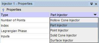
Injector 1 node and set
Type to
Part Injector.
-
Set
Inputs to
.
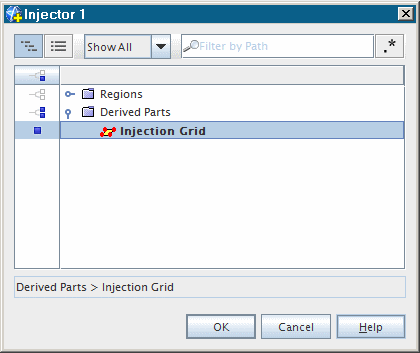
- Click OK.
-
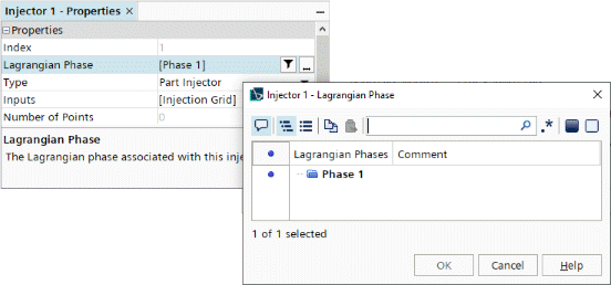
Finally set
Lagrangian Phase to
Phase 1 as shown.
The Number of Points property is 0 until the injection points are calculated during solution initialization. The conditions and values of the injector must now be set up to define the particles.
-
Edit the
node and set the following properties:
Node Property Setting Flow Rate Specification Method Mass Flow Rate Flow Rate Distribution Method Per Injector Particle Size Specification Method Particle Size Velocity Specification Method Components
The particular values for these quantities can now be set.
-
Edit the
node and set the following properties:
Node Property Setting Velocity Value [0.0, -12.901, 0.0] m/s Mass Flow Rate Value 0.027787 kg/s Parcel Streams Value 3 Particle Diameter Value 2.75E-4 m 
- Save the simulation.