Mesh Construction
Within a bounding volume defined by geometrical surfaces, Simcenter STAR-CCM+ can construct meshes for finite volume and finite element solvers.
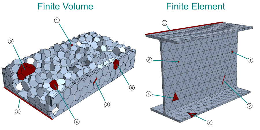
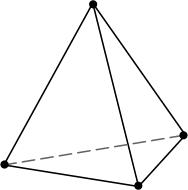
- 1 — Vertex/Node
-
A vertex or node is a point in space defined with a position vector. Other mesh entities are defined using vertices.

- 2 — Edge
- An edge connects two vertices in a straight line.
- 3 — Part Curve
-
A part curve contains one or more edges whose path defines a curve or line that you wish to retain in the final mesh—for example sharp edges or the outline of a hole that becomes a particular boundary.

Part curves are defined on a surface mesh and belong to the discretized representation. They are not used as part of the simulation analysis. - 4 — Face
-
A face comprises an ordered collection of vertices such that they define a surface in three-dimensional space.
In Simcenter STAR-CCM+, faces can have any number of vertices. Four or more faces can be used to define a 3D cell.

- Correct Face Orientation
-
You define the orientation of a face with the right-hand rule. In the above example, the face orientation is upwards (assuming you see vertex 2 as being further out of the screen than vertex 4).
If you create a mesh in an external mesh generator, make sure that the mesh conforms to this rule.
- Concave Face
-
Concavity can be calculated for any face with four or more sides and refers the amount that one part of the face “sees” another part of the same face. A non-concave cell is flat or planar. However, as the surface becomes warped or twisted, the face starts folding back on itself and produces concavity.
The concavity of a face can be determined by triangulating a face and then extend the normals of each triangle outward until they cross. The angle between the face normals is the concave angle, as illustrated below:
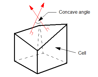
A planar face would have a concave angle of 0 degrees. Keep concave face angles as low as possible make sure that they do not exceed 89 degrees.
- 5 — Cell
-
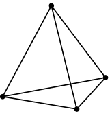
In three-dimensions, a cell is an ordered collection of faces that defines a closed volume in space. In two-dimensions, a cell is an area composed by an ordered collection of vertices. In Simcenter STAR-CCM+, cells are generated for solvers that use the finite-volume method.
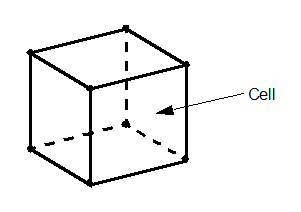
In Simcenter STAR-CCM+, cells can have any number of faces as long as there are enough faces to create a closed cell volume. The faces of a cell cannot intersect each other, except where they touch along the common edges. In three dimensions, cells of arbitrary polyhedral shape are permitted. In two dimensions, cells of arbitrary polygons are permitted.
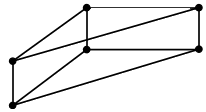
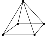
The following cell types are available.
Cell Type Diagram Element Type Tetrahedral 
10 Hexahedral 
12 Polyhedral 
42 Triangle(2D) 
5 Quadrilateral (2D) 
9 Polygon (2D) 
7 - 6 — Prism Layer Cell
- A prism layer cell is a specialized thin cell that form the prism layer. Prism layers are important for resolving the boundary layer. Prism layer cells are generated by the Prism Layer mesher. See Prism Layer Mesher.
- 7 — Element
- An element is a geometrical entity that defines a closed volume in space. In essence, an element is the finite-element equivalent of a cell. The element topology and the distribution of the unknowns within the element is defined using polynomial shape functions. For more information, see Shape Functions.
- 8 — Mid-Side Vertex
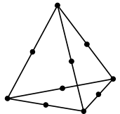
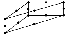
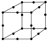
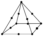
- A mid-side vertex (also known as
mid-side node) is a vertex that is located at the midpoint on an element edge.
Mid-side nodes increase the accuracy of 3D elements in solid stress analyses. For instructions on adding mid-side nodes to a solid stress mesh, see Generating a Mesh of 3D Finite Elements.
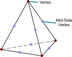
- The FE Solid Stress solver supports 3D elements without mid-side nodes (linear elements) or with mid-side nodes (quadratic elements). The meshers in Simcenter STAR-CCM+ do not generate mid-side nodes. The solver adds mid-side nodes during initialization of the solution, based on the settings that you specify for the solid region (see Region Settings: Mid-Side Vertex Option).
- The Viscous Flow and Magnetic Vector Potential finite element solvers support 2D and 3D elements. These solvers ignore any mid-side nodes on the mesh elements.
You can check whether a mesh fulfils these requirements by visualizing the Element Type field function in a scalar scene. This field function identifies each element topology with a unique number. For polygonal and polyhedral cells (see Cell Type Reference), which are not suitable for finite element analyses, the Element Type field function displays the values 7 and 42, respectively.
In addition, Simcenter STAR-CCM+ can import beam and shell elements from third-party CAE products. Imported beams and shells are intended for file-based coupling applications and are not compatible with the Simcenter STAR-CCM+ FE Solid Stress solver. See Importing CAE Models.
