Matching Vertices Manually
By default, 3D-CAD predicts the pairs of matching vertices between successive profiles in lofts. Alternatively, you can use the Vertex Matching feature to manually define the matching pairs.
You can also use vertex matching to define an alternative loft path, which enables you to twist the body between the profile sketches. During the process of matching vertices, the path between sketch profiles is determined by matching a vertex on one sketch profile with a vertex on the next profile.
| Note | To use vertex matching, the loft profiles must have the same number of vertices. |
To carry out vertex matching:
-
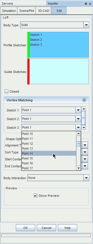
In the Loft panel, set Alignment Type to User Defined.
The Vertex Matching box appears and displays a list of sketches that are available in the loft, along with the vertices that belong to each sketch.
-
For each sketch, select a vertex from the corresponding list in the Vertex Matching box.
You can find out the name of a particular point by editing the corresponding sketch before creating the loft, and right-clicking on the point in the 3D-CAD View scene; the point name is displayed at the top of the right-click menu.

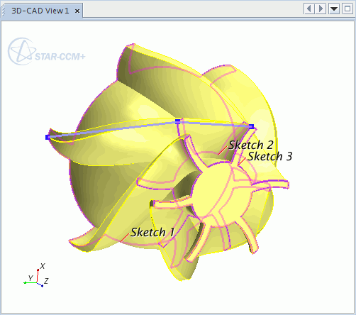
The points that you select from each sketch define a loft path. This path is displayed in the 3D-CAD View scene. You can check that you have selected the correct vertices by rotating and zooming in on the model. A preview of the loft is displayed in the 3D-CAD View scene.
- Click OK to create the loft.
