Imported Shell Elements
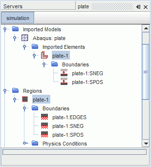
Shell elements have a positive and a negative side. When a CAE model is imported into Simcenter STAR-CCM+, a shell element defines a region, and the surfaces of the shell element are stored as boundaries within that region.


The surface that corresponds to the positive facing side of the shell are suffixed with POS, SPOS, or Front, depending on the input format. Similarly, the surface that corresponds to the negative facing side of the shell are suffixed with NEG, SNEG or Back. The positive direction is found by applying the right-hand rule to the vertex numbering on a face. If the fingers of your right hand are wrapped around the face in the direction in which vertex numbers increase, then your thumb points in the positive direction.
The shell surfaces can be used for file-based coupling in the same way as imported surfaces. When mapping onto shell surfaces, it is essential to ensure that you map to the correct side of the shell. If in doubt, activate the Check Source/Target Face Normals in the Nearest Neighbor Search Constraints group box, that is located on the Map Imported Model Data dialog. You can also visualize the direction of normals on the different surfaces. The normals of the source and target faces face each other.
[Imported Shell] Properties
| Index | Identifies the shell with a unique number (Read-only). |
| Regions | Specifies the region that is associated with the imported shell (Read-only). |
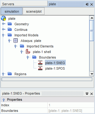
[Imported Shell Surface] Properties
| Index | Identifies the shell surface with a unique number (Read-only). |
| Boundaries | Specifies the region boundaries that are associated with the imported shell surface (Read-only). |