Identifying the Target Part Surfaces for 2D Meshing
You identify part surfaces on which a 2D mesh is required using the Badge for 2D Meshing operation. This operation identifies part surfaces that lie on the Z=0 plane. If any part surfaces lie partially on the Z=0 plane, the Badge for 2D Meshing operation fails.
-
Create a
Badge for 2D Meshing operation.
You can create any number of Badge for 2D Meshing operations, however, a part can only belong to one Badge for 2D Meshing operation.
- Right-click and select .
- In the Create Badge for 2D Meshing Operation dialog, select the parts that are required to produce a 2D mesh. It is not necessary to select part surfaces, as Simcenter STAR-CCM+ identifies the part surfaces that lie on the Z=0 plane automatically.
-
Execute the
Badge for 2D Meshing operation.
Parts and part surfaces are badged and available to select for Automated Mesh (2D) operations as follows:
 = Available to select as 2D region
 = Available to select as 2D boundary
Note Deleting a Badge for 2D Meshing operation removes the badge from the input parts and part surfaces.
Understanding the Results of a Badge for 2D Meshing Operation
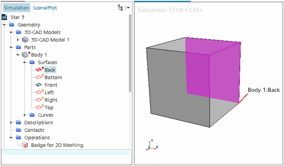
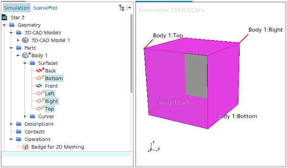
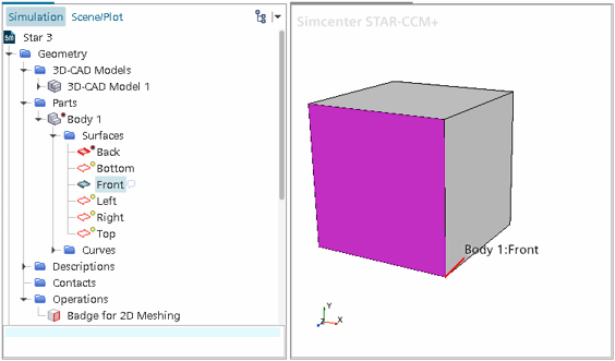
The following example shows how part surfaces on a simple three-dimensional block part are badged during a Badge for 2D Meshing operation.
On a simple block that is split into six part
surfaces, only one part surface can wholly lie on the Z=0 plane. Only the part
surface that lies on the Z=0 plane is badged as a 2D region.


The four part surfaces that are connected to the
part surface on the Z=0 plane, are badged as boundaries. The edges of these part
surfaces, that lie on the Z=0 plane, form the boundaries of the 2D region containing
the final 2D mesh.


Any part surfaces that are disconnected from the
Z=0 plane, are not badged.


Parts which contain badged part surfaces, also display a badge.