Preparing and Generating the Mesh
After assigning parts to regions and setting the boundary types, you can define the mesh settings for the volume mesh. For this simulation, you generate an anisotropic and aligned volume mesh based on an initial quadrilateral surface mesh.
The polyhedral mesher is used in conjunction with the advancing layer mesher to build a suitable mesh for the fluid volume. In order to resolve the boundary layer, the number of prism layers is set to 20 and the prism layer near wall thickness is set to a value consistent with y+ ~ 1. For external aerodynamic cases, 20-30 prism layers are typically used.
-
To set up the volume mesh:
-
Edit the node, click Expand/Contract Tree, and set
the following properties:
Node Property Setting Base Size Value 0.2 m Minimum Surface Size Percentage of Base 15.0 Surface Growth Rate Surface Growth Rate Slow Number of Prism Layers Number of Prism Layers 20 Prism Layer Near Wall Thickness Prism Layer Near Wall Thickness 1.55E-6 m Prism Layer Total Thickness Size Type Absolute Absolute Size 0.005 m -
As flow behavior far from the wing is not particularly important for this
simulation, you can specify a coarser mesh on the far-field. To do so:
-
Edit the node and set the following:
Node Property Setting Farfield Part Surfaces 
Target Surface Size Custom
Size Type Absolute Absolute Size 3.0 m
-
Edit the node and set the following:
-
To capture the turbulent flow conditions that occur behind the wing, set up a
wake refinement control:
-
Edit the node and set the following:
Node Property Setting Wake Refinement Part Surfaces
Specify wake refinement options Activate
Distance 5.0 m Spread Angle 5.0 deg
-
Edit the node and set the following:
-
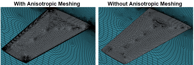
To use anisotropic meshing:
-
To refine the mesh on the leading edge:
-
Edit the node and set the following:
Node Property Setting Leading Edge Part Curves
Specify anisotropic surface size settings Activate Specify anisotropic mesh distribution between close Part Curves Activate
Number of Constant Layers 3 Size Type Absolute Absolute Size 0.001 m Size Type Absolute Absolute Size 3.0E-4 m
-
Edit the node and set the following:
-
To refine the mesh on the side:
-
Edit the node and set the following:
Node Property Setting Wing Side Part Curves
Specify anisotropic surface size settings Activate Specify anisotropic mesh distribution between close Part Curves Activate
Number of Constant Layers 3 Size Type Absolute Absolute Size 3.0E-4 m Size Type Absolute Absolute Size 2.5E-4 m
-
Edit the node and set the following:
-
To refine the mesh on the trailing edge:
-
Edit the node and set the following:
Node Property Setting Trailing Edge Part Curves , Trailing Edge Side and Upper Trailing Edge
Specify anisotropic surface size settings Activate Specify anisotropic mesh distribution between close Part Curves Activate
Number of Constant Layers 6 Min Number of Layers 3 Size Type Absolute Absolute Size 4.25E-4 m Size Type Absolute Absolute Size 1.5E-4 m
-
Edit the node and set the following:
-
Click
 (Generate Volume
Mesh) in the toolbar or select Generate Volume
Mesh in the Mesh menu.
(Generate Volume
Mesh) in the toolbar or select Generate Volume
Mesh in the Mesh menu.
The run and progress of the meshers are displayed in the Output window.
-
To display the volume mesh, from the Vis
toolbar, click
 (Create/Open Scenes) and select
Mesh.
(Create/Open Scenes) and select
Mesh.
- Save the simulation.