Creating a Spherical Far-Field Boundary
In this tutorial, you create a sphere where the outer surface represents the far-field conditions of the flow.
To create a spherical fluid domain:
-
In the object tree, right-click the node and select Edit.
The 3D-CAD environment launches. Within 3D-CAD, an object tree that is specific to the 3D-CAD model is displayed.
-
Create a plane by transformation for the domain:
- Right-click the node and select .
- In the Plane By Transformation panel, set the Translation Vector to [0.0, 0.0, 0.2] and click OK.
A sketch plane feature, Plane 1 is added to the Features node. -
Create a sketch for the domain:
-
In the Sketch panel, click
 (View
Normal to Sketch Plane).
(View
Normal to Sketch Plane).
-
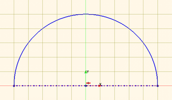
Use the
 (Create Center-Point Circular Arc) tool to
draw an arc with a radius of 50 m. Three mouse clicks are required:
(Create Center-Point Circular Arc) tool to
draw an arc with a radius of 50 m. Three mouse clicks are required:
- Click position [0.0 m, 0.0 m] to define the center point.
- Click position [50.0 m, 0.0 m] to define the start point.
- Click position [-50.0 m, 0.0 m] to define the end point.
-
Click
 (Create Line) and
draw a horizontal line of length 100 m starting
at -50 m and ending at 50
m and passing through the origin. To end the line, press
<Esc>.
(Create Line) and
draw a horizontal line of length 100 m starting
at -50 m and ending at 50
m and passing through the origin. To end the line, press
<Esc>.
-
Right-click the line and select Set As
Construction.
-
In the Sketch panel, click
-
Use the revolve tool to create the sphere:
- In the 3D-CAD feature tree, right-click Sketch 1 and select Revolve.
- In the Revolve panel, set Angle to 180.0 deg and click OK.
- In the 3D-CAD View scene, rename the new surface to Farfield. (To rename a surface, right-click the surface and choose Rename).
-
In the Vis toolbar, click
 (Save-Restore-Select Views) and select .
-
Use the fill hole tool to cap the sphere and convert it to a solid body:
- In the 3D-CAD View scene, double-click the free edge (displayed in green) to select all connected free edges.
- Right-click the selection and choose Fill Surface.
- In the Fill Surface panel, click OK.
- In the 3D-CAD View scene, rename the new surface to Symmetry.
-
To create the fluid volume:
- Under Body Groups, right-click the Body 2 node and select .
-
In the Subtract Bodies panel, to the
right of the Tool Bodies selection box, click
 (Open Selector).
-
Within the Select Tool Bodies panel,
select Body 1. Click (Close Selector).
- Click OK.
- Under the Body Groups node, rename the Body 2 node to Fluid.
- At the bottom of the object tree, click Close 3D-CAD.
- Save the simulation.