Using Variable Radius to Create a Fillet
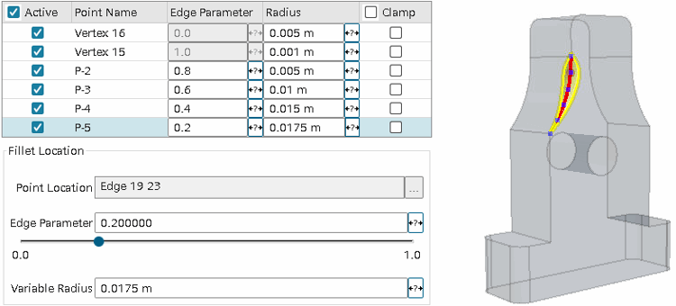
The variable radius fillet provides several controls over the fillet along its edge path. You can choose to set radius values at specific points, or to use conic sections defined by parameter Rho. This feature is useful for complex geometry such as turbine blades.
-
To create a fillet:
- Right-click on an edge in the 3D-CAD View window and select Create Fillet.
- Click
 (Create
Fillet) in the 3D-CAD toolbar. If the 3D-CAD toolbar is not
visible, click and activate 3D-CAD from the list.
-
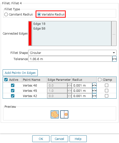
In the Fillet panel, select the
Variable Radius option.
-
To add to the edge selection, click within the Connected
Edges box, press and hold the <CTRL>
key and select further edges in the graphics window.
Edges must to form a single connected chain on a single body. For closed loop edges, you must define two points on the edge.
- To remove one or more edges, right-click on selected edges in the list and choose the corresponding action.
-
Set Fillet Shape to either
Circular or Conic.
To achieve a particular type of conic shape, alter the Rho value as follows:
- Elliptic: 0 < Rho < 0.5
- Parabolic: Rho = 0.5
- Hyperbolic: 0.5 < Rho < 1
- If the feature fails, then adjust the tolerance value. The tolerance value is based on the size of the input entities. For example, if an edge is 0.1 mm long on a small geometry, a high tolerance will completely ignore or eliminate the desired details in the model.
-
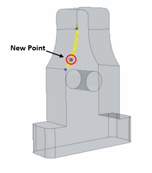
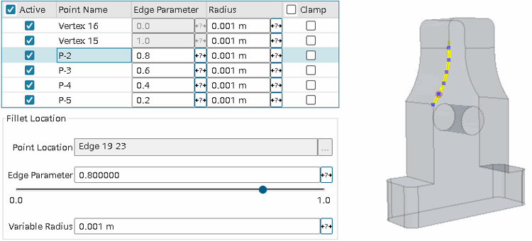
To define additional locations on which to set the radius:
If you define a control point along an edge, but wish to check
how the fillet looks without it, then you can deactivate the control point without
deleting it.
-
To remove the influence of a control point on the fillet, in the table of
points, do one of the following:
- Deactivate the Active property next to the point.
- Right-click either the Point Name, Edge Parameter, or Radius column of the required table row and select Deactivate.
You can reactivate points in a similar manner.
Clamping allows you to impose a zero rate of change of radius on the fillet
as it passes through a chosen point. Clamping is valid on start and end points as
well as intermediate points.


-
To apply clamping to a point, select its row in the point table and activate
Clamp.
The right-click menu on a Point Row, Edge Parameter, or Radius column provides the same option.
