Applying a Chamfer Feature
To apply a chamfer:
-
Either:
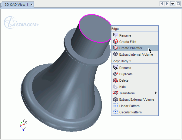
- Right-click on an edge or face in the
3D-CAD View scene and select
Create Chamfer.
- Click
 (Create Chamfer) in the 3D-CAD toolbar.
- Right-click on an edge or face in the
3D-CAD View scene and select
Create Chamfer.
- Select any additional edges and faces in the 3D-CAD View window. To make the selection of faces or edges more easily, use the Selection Filter. (See Filtering the Selections.) You can select multiple edges/faces at once by holding down the <Ctrl> key.
- In the Distance textboxes, enter the chamfer size. These values determine the distance that the chamfer extends from the selected edge, or edges. It is not possible to determine which face each distance is applied to.
- If the feature fails, then adjust the tolerance value. The tolerance value is based on the size of the input entities. For example, if an edge is 0.1 mm long on a small geometry, a high tolerance will completely ignore or eliminate the desired details in the model.
-
If necessary, you can expose each distance as design parameter by clicking the
 (Expose Parameter) button.
The number of edges and faces that have been selected is shown next to the Number of Selected Edges and Number of Selected Faces fields respectively. A preview of the chamfer feature is displayed in the 3D-CAD View scene, and allows you to visualize the chamfer feature and switch the two distances. The chamfer is shown in yellow, while the edges and faces that are used to create the chamfer are shown in purple.
(Expose Parameter) button.
The number of edges and faces that have been selected is shown next to the Number of Selected Edges and Number of Selected Faces fields respectively. A preview of the chamfer feature is displayed in the 3D-CAD View scene, and allows you to visualize the chamfer feature and switch the two distances. The chamfer is shown in yellow, while the edges and faces that are used to create the chamfer are shown in purple.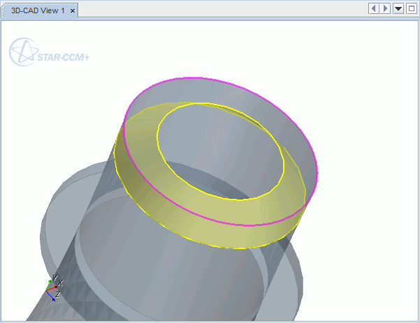
- Click OK to apply the chamfer to the selected edges.
A node is added to the feature tree.
To modify the dimensions of the chamfer, right-click on the Chamfer node and select Edit...