Creating a Streamlines Scene
Create a scene to display the streamlines inside the cyclone separator.
- Create a Geometry Scene.
- Switch to the Scene/Plot tree and rename the Geometry Scene 2 node to Streamlines.
Streamlines are created as a derived part. In this case, the streamlines are tracked from the cyclone inlet.
-
Switch to the Simulation tree and create a streamline
derived part as follows:
Define the scene
settings:
- Click Scene/Plot.
- Select the node and set Opacity to 0.3.
Adjust the appearance of the streamlines to display ribbons instead of the
default lines:
- Select the node and set Mode to Ribbons.
Adjust the scalar field of the streamlines to display velocity:
- Select the node.
- Set Function to .
To animate the streamlines:
-
Set the following properties:
Node Property Setting Streamlines 
Animation Mode Tracers  Streamline Settings
Delay between tracers (sec) 6 Head size 0.01 Tail Length (sec) 1
To extend the streamlines through the fluid domain up to the outlet, increase the maximum propagation property. This property defines how far the streamlines are propagated through the fluid domain from the starting points.
-
Select the node and set Maximum Propagation to
15.
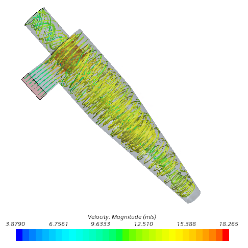
The streamlines appear as follows:
-
In the Animation toolbar:
-
Click
 (Play)
-
To stop the animation, click
 (Stop)
-
Click
- Save the simulation.