Generating the Volume Mesh
After assigning parts to regions, you can define the mesh settings for the simulation to generate a polyhedral volume mesh. For this simulation, the polyhedral mesher is used in conjunction with the advancing layer mesher to build a mesh suitable for predicting the swirling flow inside the cyclone.
In this simulation, in order to resolve the swirling motion of the fluid, you apply a volumetric mesh refinement through the middle of the cyclone. You also apply refinement on the inlet.
To set up and generate the volume mesh:- Right-click the node and select .
-
In the Create Automated Mesh Operation dialog:
An automated mesh operation is added to the Operations node.
-
Edit the node and set the following properties:
Node Property Setting Base Size Value 0.0125 m Target Surface Size Percentage of Base 80.0 Minimum Surface Size Percentage of Base 30.0 Surface Curvature # Pts/circle 72 Surface Growth Rate User Specified 1.3 Number of Prism Layers Number of Prism Layers 5 Prism Layer Stretching Prism Layer Stretching 1.2 Prism Layer Total Thickness Size Type Absolute Absolute Size 0.012 m Volume Growth Rate Volume Growth Rate 1.1
Two shape parts are used in separate volumetric control operations
to refine the mesh. The mesh refinement in the middle of the geometry and around the inlet
are created to capture the turbulent behavior of the flow accurately.
-
For the core refinement in the middle of the cylinder, create a cylinder shape part:
-
For refining the mesh around the inlet, create a block shape part:
Volumetric controls allow you to set custom mesh conditions for any
geometry that falls within the volume covered by the control. Each control requires a part
specification that defines the volume.
-
To create the core mesh refinement:
-
Edit the node and set the following properties:
Node Property Setting Cylinder Refinement Parts Cylinder  Controls
 Surface Remesher
Customize Size Activated Polyhedral
MesherCustomize Polyhedral Mesher Activated Values
Custom Size
Percentage of Base 50.0
-
Edit the node and set the following properties:
-
To create the inlet refinement:
-
Edit the node and set the following properties:
Node Property Setting Inlet Refinement Parts Block Controls
Surface Remesher
Customize Size Activated Advancing Layer
MesherCustomize Total Thickness Activated Polyhedral
MesherCustomize Polyhedral Mesher Activated Values
Custom Size
Percentage of Base 50.0 Size Type Absolute Absolute Size 0.008 m
-
Edit the node and set the following properties:
Now that all mesh settings are defined, you can generate the volume
mesh.
-
Click
 (Generate Volume
Mesh) in the toolbar or select Generate Volume Mesh
in the Mesh menu.
(Generate Volume
Mesh) in the toolbar or select Generate Volume Mesh
in the Mesh menu.
The run and progress of the meshers are displayed in the Output window.
-
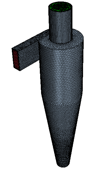
To display the volume mesh, from the Vis toolbar,
click
 (Create/Open Scenes) and select Mesh.
The volume mesh is displayed below.
(Create/Open Scenes) and select Mesh.
The volume mesh is displayed below.