Creating the Fluid Region
To use 3D-CAD geometry in a simulation, you first convert the model to geometry parts, and then assign these parts to regions. After creating the regions, you define boundary types on flow boundaries.
-
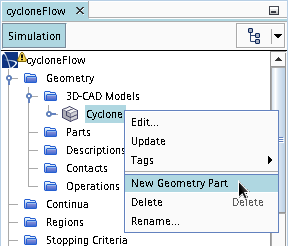
Right-click the node and select New Geometry Part.
-
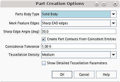
In the Parts Creation Options dialog, click
OK to close the dialog. The default settings are
acceptable.
All the bodies that are combined within the model are shown under the manager node.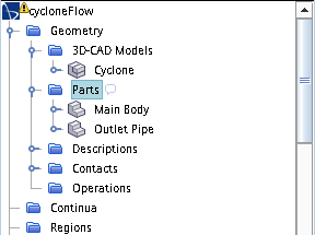
To define the computational domain, assign the parts to regions. In this
tutorial, there are two regions, one for each part.
- Expand the node and multi-select the Main Body and Outlet Pipe nodes.
- Right-click on one of the selections and choose Assign Parts to Regions....
-
In the Assign Parts to Regions dialog, select:
- Create a Region for Each Part
- Create a Boundary for Each Part Surface
-
Click Apply then Close.
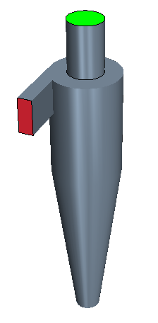
Two regions are created with boundaries that define the inlet, outlet, and interfaces between the two regions.
- To view the regions, create a geometry scene.
Before generating the volume mesh, one of the best practices
is to set the boundary types for flow boundaries. By default, the prism layer mesher
does not create prism layer cells across the surface of flow boundaries. Prism layer
cells are generally only necessary on wall boundaries.
-
To set the boundary types:
To define the interfacing sides of the outlet pipe as a baffle:
- In the simulation tree, expand the Interfaces node.
- Select the Main Body/Outlet Pipe 2 node and set Type to Baffle Interface.
- Save the simulation.