Modeling the Propeller by Using the Virtual Disk Model
For this simulation, you model the effects of the propeller on the ship using the body force propeller method. This method belongs to the virtual disk model.
Using the virtual disk for a propeller requires you to define the following items:
-
dimensions and location of the disk
-
orientation of the disk axis. This orientation defines the direction of the thrust force.
-
propeller performance data, where the thrust coefficient K_T and the torque coefficient K_Q are provided as a function of advance ratio J
- velocity plane on which to obtain an average velocity and density for the inflow surface of the virtual disk
To set up the virtual disk model:
- Right-click the node and select .
- Edit the Virtual Disk node and set Method to Body Force Propeller Method.
- Right-click and select .
- Navigate to the motion folder of the downloaded tutorial files, select BSeries_Z5_BAR1p05_PD0p723.csv, and click Open.
-
Edit the node and set the following properties:
Node Property Setting Propeller Curve Method Table (J)  Table (J)
Table BSeries_Z5_BAR1p05_PD0p723 Table: J J Table: Kt KT Table: Kq KQ Table: Eta ETA Disk Geometry Inner Radius 0.036 m Outer Radius 0.18 m Origin [-6.307, 0.0, -1.25] m,m,m  Normal And Coordinate System
Coordinate System Laboratory -> Ship-CSys Disk Normal [1.0, 0.0, 0.0] Inflow Specification Method Inflow Velocity Plane  Inflow Velocity Plane
Inflow Plane Radius 0.198 m Inflow Plane Offset 0.036 m  Induced Velocity Correction
Option
Induced Velocity Correction Off RotationRate (n) Rotation Rate 2300.0 rpm Note You must associate the Coordinate System property that defines the direction of thrust with the local coordinate system of the ship body, here identified as Ship-CSys. This association establishes the connection between the thrust produced by the virtual disk and the DFBI motion of the ship. The ship coordinate system moves with the ship according to the fluid forces calculated by the DFBI model.
-
Expand the
and drag and drop the
Virtual Disk-CSys 1 node into the currently active
Geometry 1 scene.
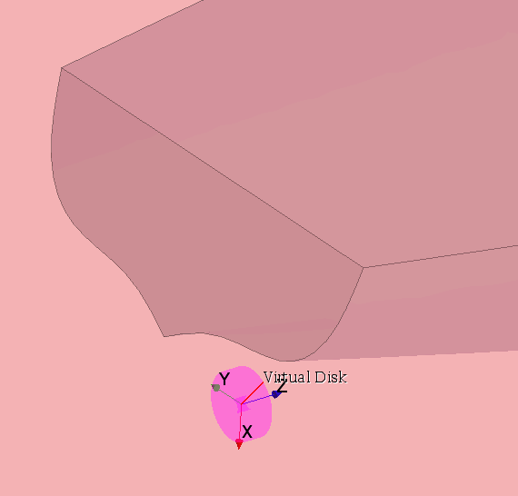
The virtual disk local coordinate system is displayed in the scene. The thrust produced by the virtual disk acts in the Z direction of this coordinate system.
-
To visualize the virtual disk, select the
Virtual Disk node within
Physics Continuum 1 and zoom in on the virtual disk.

- Save the simulation.