Mesh Morpher Solver Reference
The Mesh Morpher solver is designed to control the morphing motion calculations with specialized properties. It becomes available when a region has the morphing motion selected.
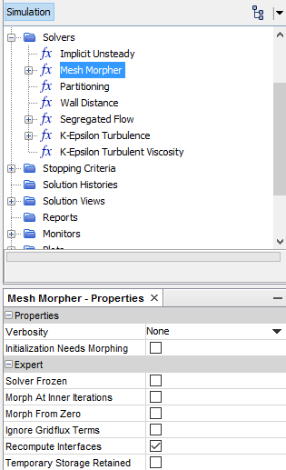
Mesh Morpher Solver Properties
Properties can be set under . The following properties are the same for BSpline and RBF.
- Verbosity
- Provides additional output for this value while the simulation is running. This property is useful for debugging problems when they occur.
- None—Leaves output at its default.
- Low—Adds messages as to which region is morphed.
- High—Generates precise equation information about the morphing process as the solver converges.
- Initialization needs morphing
- Selecting this option causes the morpher to run when the simulation is initialized. Use this option when the control point specifications at time zero define an initial deformation of the mesh. When activated, the morpher runs at time zero. When deactivated, the morpher does not run at time zero, but runs during the first time-step to apply deformations at time equal to .
- Solver Frozen
- When On, the solver does not update any quantity during an iteration. It is Off by default. This is a debugging option that can result in non-recoverable errors and wrong solutions due to missing storage. See Finite Volume Solvers Reference for details.
- Morph At Inner Iterations
- The morpher updates the mesh position at each
inner iteration during the time-step. This action is only meaningful for
cases where some boundary condition depends on the solution; it is off by
default to reduce computational costs. For FSI, if this setting is initially
deactivated when running a simulation, the Fluid Structure Coupling solver
activates it whenever the change in volume of the cells adjacent to the
fluid-solid interface becomes significant.
For a DFBI morphing motion, this option is activated by default and cannot be deactivated. DFBI uses an implicit algorithm for coupling fluid flow and body motion, which requires a morphing update at each inner iteration. See also: Combining DFBI Motion with Morphing.
- Morph From Zero
- When activated, the morpher calculates the current positions of the mesh vertices from the initial mesh configuration, rather than the configuration at the previous update. This behavior is helpful for periodic motions, to ensure that the mesh is also periodic, and when automatic thinning is applied (RBF morpher only).
- Activating this option increases performance
and robustness when Morph At Inner
Iterations is activated.
When this option is activated:
- During the first iteration, the morpher deforms the mesh starting from the initial undeformed configuration.
- From the second iteration onwards, the morpher deforms the mesh incrementally from the mesh configuration reached in the previous iteration.
The following illustration shows the morphing process with and without Morph From Zero:

To avoid increasing the morpher runtime, deactivate this option when the total displacement relative to the initial coordinates becomes large.
- Ignore Gridflux Terms
- When this option is activated, the mesh still moves but the “grid” flux is not included in the transport equations. This option provides more stability when marching towards a steady-state solution with an unsteady solver. It is also useful when you are simply adjusting the shape of the region without solving the transport equations.
- Recompute Interfaces
- When activated, at each time-step, Simcenter STAR-CCM+ recomputes all
direct interfaces, that is, interfaces with
Imprinted or Conformal
connectivity. For more information on the available types of interface, see
.
Use this option only if the morphing changes the mesh in different ways on opposite sides of the interfaces.
- Temporary Storage Retained
- Specifies whether to retain temporary storage at the end of the iteration, or not. Examples include the ap coefficients, the residual, the corrections, the reconstruction gradients, and the cell gradients. These quantities become available as field functions during subsequent iterations.
- Boundary Layer Morphing
- Depending on the specified settings, the morpher updates the mesh at each inner iteration within a time-step, or only once per time-step. When motion reaches convergence within a time-step, the mesh changes between consecutive updates become small.
Mesh Morpher Solver Controls
- Morpher Tolerance
- Available for BSpline and RBF. Non-dimensional parameter that is used to specify acceptable accuracy in morphing. This parameter is multiplied by the longest edge-length of the bounding box enclosing the morphing region.
If the mesh to be morphed contains extremely long and thin prism layers cells, you are advised to reduce the Morpher Tolerance to a value between 10E-7 to 10E-9. This setting can avoid negative cell volumes occurring during morphing.
- Skip Thinned Vertex Corrector
- Only available for RBF. When activated, this option prevents the RBF morpher from attempting to correct thinned vertices. When the Vertex Thin Factor on a boundary is set to less than 1, the boundary vertices excluded due to thinning are initially moved according to the interpolation field. It is possible, however, that the final position of these thinned vertices is not precisely the position they would have obtained had they been moved according to the specified displacement on the boundary. A small error could result for other reasons—even if vertex thinning is not used. To correct this error, a thinned vertex corrector algorithm is executed within the interpolation process. The corrector algorithm ensures that the thinned vertices receive the same displacement as the control vertices taken from their respective boundaries.