Specifying the Input Files
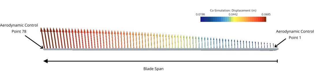
The deformation and twist of the 1D beams are described in two seperate files. The motion file contains displacement information at aerodynamic control points along the span of the blade. The twist table file describes the spanwise pitch of the undeformed blade geometry.
The motion file contains the displacements at 78 spanwise aerodynamic control points (indicated by nspan) for each azimuth angle, . The pitch data in the twist table file is also measured at the control points. 361 azimuth angles are evaluated (indicated by npsi) corresponding to measurements at to .
In the motion file, the location of the control points are described using the blade quarter chord information: xqc, yqc, and zqc represent the control point x, y, and z coordinates respectively. For example, the first five locations in the motion file are:
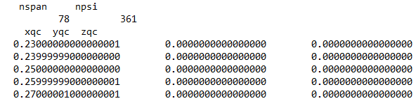

PSI= 180.0, indicates this is the displacement data at .
To account for the effect of blade rotation and deformation on the fluid mesh, Simcenter STAR-CCM+ uses the imported motion file as an input for the mesh morpher. The fluid mesh adjusts as the rotor rotates in response to the imported beam displacements.The twist table file along with the rotational deformation in the motion file describe the blade pitch at each control point for a given azimuth angle.
To import the blade twist data in Simcenter STAR-CCM+:
- Right-click the node and select .
- In the Open dialog, navigate to your working directory, select the AFDD_blade_twist.csv file and click Open.
- Select the node and rename it to Rotor 1.
- Select the node.
-
Select the Directory property and click
 (Custom Editor).
- In the Save dialog, navigate to your working directory, select the AFDD_hart-II_motion.in file and click Save.
- Select the node and set Option to Rotation X-Y-Z Axis.
-
Select the Output File node and set File Extension to .out.
During the simulation, Simcenter STAR-CCM+ automatically exports the internal boundary data (fluid pressure and wall shear stress) to this file and saves it to your working directory.
-
Select the node and set Sampling Frequency to
1.0 deg.
By default, Start Sampling and Sampling Period are set to 0 and 360. Hence, you export data for every one degree change in azimuth angle between and .
- Save the simulation.