Creating the Coupling Zones
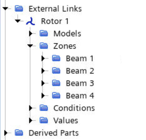
To exchange data between the Simcenter STAR-CCM+ boundaries and the beam structures defined in the external file, you create coupling zones. You require two zones for each rotor blade—one zone for the external beam and one for the corresponding Simcenter STAR-CCM+ boundary. These zone pairs exchange data throughout the simulation.
- Expand the node and rename Zone 1 to Beam 1.
- Select Beam 1 and set Zone Type to Curve Zone.
- Select the node and set Continuum to External.
-
Expand the node and set the following properties:
Node Property Value Coordinate System Coordinate System Radius Radius ${Xblade_radius} Twist Angle Method Table (Twist Angle)  Table (Twist Angle)
Table AFDD_blade_twist Table: Data column0 -
Create the beam zone for the second blade:
- Right-click the Beam 1 node and select Instance Zone.
- Rename Beam 1 Instance 1 to Beam 2.
-
Create two more instances of the Beam 1 zone: one called
Beam 3 and one called Beam
4.
As the rotor blades are spaced 90 degrees from each other
about the origin, you specify the angle offset of each beam zone.
- Select the node and set Angle Offset to 90.0 deg.
- Set the Angle Offset for Beam 3 and Beam 4 to 180.0 deg and 270.0 deg respectively.
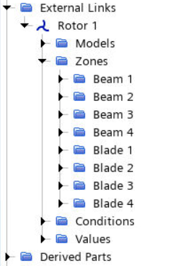
To create the surface zones that represent the internal blade
boundaries:
-
Right-click the node and select New.
The default Zone Type, Surface Zone, is appropriate for the Simcenter STAR-CCM+ blade boundaries.
- Rename Zone 1 to Blade 1.
- Select the node and set Continuum to Air.
- Select and set Parts to .
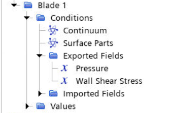
Specify the fields that are exported to the ouput
file.
-
Expand the node.
Pressure is exported by default.
-
Right-click the Exported Fields node and select .
-
Create a surface zone for the second blade:
- Right-click Blade 1 and select Instance Zone.
- Rename Blade 1 Instance 1 to Blade 2.
- Select and set Parts to .
-
Using the same procedure, create two more instances of the Blade
1 zone (one called Blade 3 and one called
Blade 4) and set their Parts
to the Blade 3 and Blade 4
boundaries respectively.
- Save the simulation.