Forces and Moments
Simcenter STAR-CCM+ computes the resultant force and moment from the contributions of the individual forces and moments defined for the 6-DOF body.
The resultant force and moment acting on the body can be written as:
- represents external forces that are generated by multi-body constraints or joints, and represents all other forces such as flow, gravity, and user-defined forces (see External Forces and Moments).
- represents external moments that result from multi-body constraints or joints, and represents all other moments (see External Forces and Moments).
- is a time-ramping function that is defined as: (4881)
where is the user-specified release time and is the specified ramp time.
External Forces and Moments
- User-defined Forces and Moments
- Simcenter STAR-CCM+ allows you to define external forces and moments
directly. You can define:
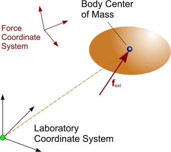
- Forces acting on the 6-DOF body at its center of mass:
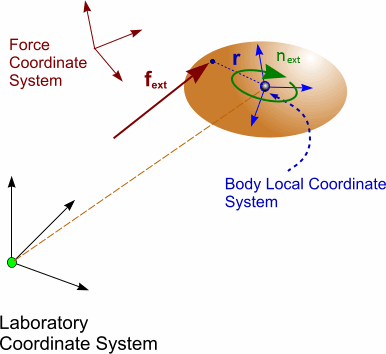
- Forces acting on the 6-DOF body at a specified
location:
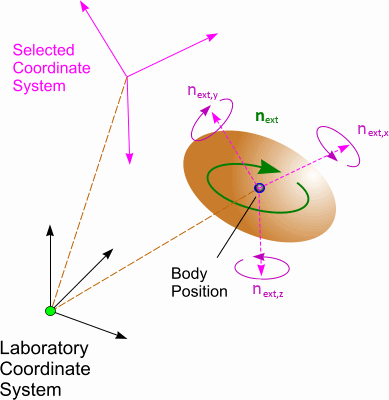
- Moments acting on the 6-DOF body with respect to the
body position:
- Forces acting on the 6-DOF body at its center of mass:
In addition to user-defined forces and moments, Simcenter STAR-CCM+ provides the following predefined types:
- Gravity Force
- The gravity force is defined as: (4882)
- Fluid Force and Moment
- The force and moment exerted by the surrounding fluid can be written as:
(4883)
and
(4884)where:- and are, respectively, the pressure and shear stress acting on face
- is the area vector of face
- is the distance vector from the body center of mass to the center of face
- Torsional Spring Moment
- The torsional spring moment mimics the effect
of a torsional spring on a rotating body. This moment acts to rotate the
body into the angular position that is given by the relaxation angle.

- Damping Moment
- The damping moment acts with respect to the
position of the body in opposition to the angular velocity vector.
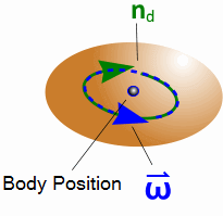
The damping moment is defined using a linear damping function:
(4886)where is the angular damping constant.
- Damping Force
- The damping force acts on the body at the
body position and in the opposite direction to the body’s velocity vector.

- DEM Force and Moment
- The DEM force and moment is calculated by the
DEM Boundary Forces model. It computes the DEM contact force acting on the
DFBI body resulting from an explicit coupling between DEM particles and the
DFBI body. See Contact Force.
The total force acting on the DFBI body is the sum of the forces on the
individual faces: (4888)
The total moment is:
(4889)where is the distance vector from the body position to the center of face .
- Electromagnetic Force and Moment
- The electromagnetic force and moment represent the magnetic force (Eqn. (4350)) and torque (Eqn. (4352)) that act on a 6-DOF body in presence of electromagnetic fields. For more information, see Electromagnetic Force.
- Virtual Disk Force and Moment
- The virtual disk force and moment represent
the forces and moments that act on a 6-DOF body when a virtual disk is used
to move the body.
Forces and moments of a virtual disk can be calculated in different ways depending on the virtual disk method active on a virtual disk. See different methods in Virtual Disk Model. The forces and moments are defined with respect to the virtual disk local coordinate system. See also Local Coordinate System.
To apply the values from disk to DFBI body, forces and moments must be transformed to the laboratory coordinate system as follows:
(4890)(4891)where
- is the moment in the virtual disk local coordinate system.
- is the force in the virtual disk local coordinate system.
- is the transformation matrix from the virtual disk local coordinate system to the laboratory coordinate system.
- and are the force and moment in the laboratory coordinate system.
- is the distance vector between the body position and the virtual disk's origin.
The transformation for a vessel impulsed with a Body Force Propeller is illustrated below:
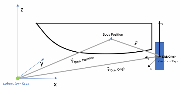
(4892)Both body position and disk origin are specified in the laboratory coordinate system. Forces and moments from the virtual disk model are calculated first in the disk local coordinate system.