Preparing a Scalar Scene
A scalar scene is created to show the velocity magnitude on a section plane through the center of the s-bend. Use this scene to visualize the solution while the simulation is running.
- Create a scalar scene.
- Right-click the node and select
-
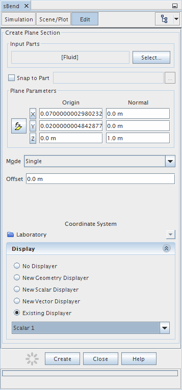
In the Create Plane Section panel, set the following
values:
Property Value Input Parts Fluid Normal [0, 0, 1] m Display Existing Displayer Dropdown menu Scalar 1 The completed dialog is shown below.
-
Click
Create and then
Close.
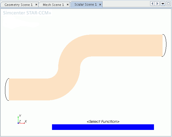
Scalar Scene 1 is shown below.

- Click the Scene/Plot tab.
- Select the node and set the Function to .
- Select the Scalar 1 node and set the Contour Style to .
-
Select the
node and set
Color Map to
purple-red (large difference).
This color bar option helps to identify the rapid change of velocity as the flow passes round the bend.
Also create a vector scene using the same plane section as before.
- Create a vector scene then return to the panel showing the Simulation tree.
-
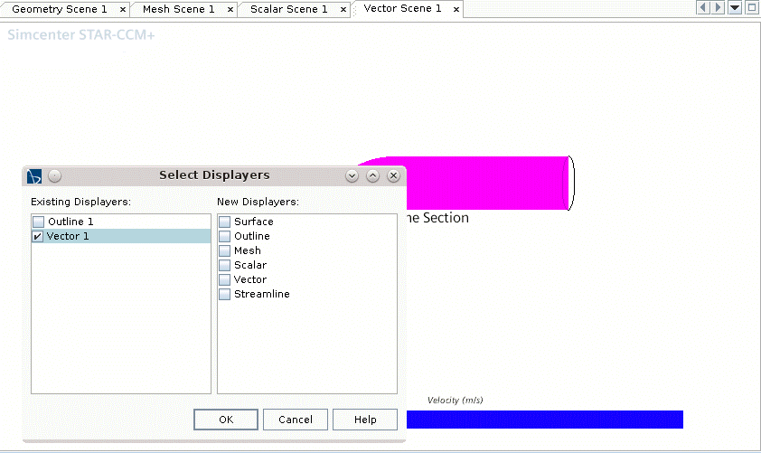
Using the drag-and-drop method, add the section plane from the node to the scene within displayer Vector 1.

- Within the Scene/Plot panel, select the node and set Color Map to blue-red balanced.
- Click Simulation at the top of the tree.