Defining the Wing Motion
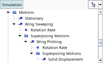
To account for the wing total displacements, you superpose three motions that move the solid mesh according to the prescribed sweeping motion, the prescribed pitching motion, and the deformation calculated by the stress solver.
To create the sweeping motion:
- Right-click the node and select .
- Rename the node to Wing Sweeping.
Specify the coordinate system for the sweeping motion. The initial simulation contains predefined coordinate systems that define the initial orientation before the motion starts:
-
Select the
node and set
Coordinate System to
.
You define the remaining properties of the sweeping motion in the next section.
Superpose the pitching motion on the sweeping motion:
- Right-click the node and select .
-
Rename the
Rotation node to
Wing Pitching.
When you create the pitching motion, Simcenter STAR-CCM+ automatically creates the coordinate system in which the motion is defined, Wing Pitching-CSys:
The coordinate system for the pitching motion moves according to the parent sweeping motion. To reflect this, Simcenter STAR-CCM+ automatically sets the following properties:Motion Node Property Setting Wing Sweeping Managed Coordinate Systems Wing Pitching Coordinate Systems You define the remaining properties of the pitching motion in the next section.
Modify the properties of the
Wing Pitching-CSys coordinate system so that it is oriented according to the initial stroke angle. As a shortcut, you can copy and paste the properties of the
Stroke_Fixed_InitialConfiguration node onto the
Wing Pitching-CSys node.
- Expand the node.
- Right-click the Stroke_Fixed_InitialConfiguration node and select Copy.
- Right-click the node and select Paste.
Finally, superpose the
Solid Displacement motion, which accounts for the displacements calculated by the solid stress solver:
-
Right-click the
node and select
.
To assign the superposed motions to the wing region:
- Select the node and set Motion to .
- Save the simulation.