Generating the Mesh
The starting simulation contains predefined mesh operations that are fully set up and ready for execution. These operations prepare the geometry parts and generate appropriate meshes for the fluid and solid regions.
-
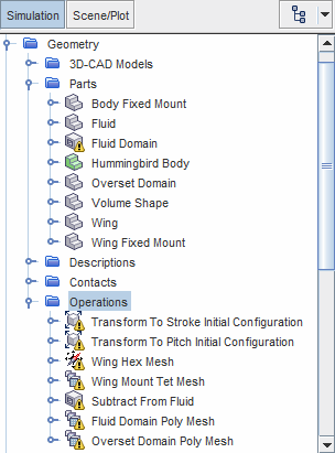
Expand the
node.

-
Right-click the
Operations node and select
Execute All.
The meshing pipeline executes the following steps:
- Rotates the wing parts (wing and wing mount) in order to have an initial stroke angle of 70° and an initial pitch angle of -40°.
- Generates a finite element mesh for the wing components (hexahedral mesh for the wing and tetrahedral mesh for the wing mount).
- Creates the fluid region by subtracting the hummingbird body from the fluid part.
- Generates a polyhedral mesh for the parts that are assigned to the fluid and overset regions.
- When the mesh generation is complete, create a mesh scene.
During the solution, you can use this mesh scene to visualize the wing motion while the solvers run. For this purpose, you create a derived part that represents the stroke plane in which the sweeping motion is confined:
- Right-click the Derived Parts node and select
-
In the
Create Plane Section dialog, set the following properties:
Property Setting Input Parts and Overset Domain (Deselect the wing region) Origin [0.0, 0.0, 0.0] m,m,m Normal [0.0, 0.0, 1.0] m,m,m Displayer No Displayer - Click Create then Close.
- Rename the node to Stroke Plane.
In the mesh scene, you define two displayers—one for the wing, and one for the fluid. For the fluid, you visualize the mesh on the hummingbird body boundary and the projection of the fluid and overset meshes on the stroke plane:
- Expand the Scenes node.
- Right-click the Mesh Scene 1 node and select .
- Rename the Mesh 1 displayer to Wing Mesh and the Mesh 2 displayer to Fluid Mesh.
-
Edit the Mesh Scene 1 node and set the properties of
each displayer as follows:
Node Property Setting Fluid Mesh Opacity 0.5 Surface Activated  Parts
Parts
Parts Wing Mesh Color Mode Constant  Parts
Parts
Parts (Deselect the fluid and overset regions)  Color
Color
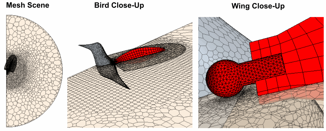
Color Red The mesh appears as shown below: