Generating the Volume Mesh
You generate a trimmed cell volume mesh without prism layers. To improve the accuracy of the calculation, you refine the heat exchanger core by using a block-shaped volumetric refinement. The individual heat exchanger parts are meshed per-part, which makes the mesh non-conformal at the interface. You are required to use per-part meshing to mesh the two collocated core parts. Alternatively, you can use a Volume Mesh Pattern to mesh the duplicated core part.
- Right-click the node and select .
-
In the Create Automated Mesh Operation
dialog:
- Select the node and activate Per-Part Meshing.
- Select the node and activate Perform Mesh Alignment.
-
Edit the
node and set the following properties:
Node Property Setting Base Size Value 2.56 cm Percentage of Base 1 Mesh Alignment Location Location [-0.166693, 0.293814, 0.126133] m -
Create a block shape part around the core. This shape is for the volumetric
controls that define mesh refinement.
-
Create a volumetric control and select the shape that defines the source:
-
Edit the node and set the following properties:
Node Property Setting Volumetric Control Parts Block  Controls
 Surface
Remesher
Surface
Remesher
Customize Size Activated Trimmer
Customize Isotropic Size Activated Values
Custom
Size
Size Type Absolute Value 0.64 cm
-
Edit the node and set the following properties:
-
To start the mesh generation process, click
 (Generate Volume
Mesh).
The output from the meshers is shown in the Output window. When the meshing process is complete, the message Volume Meshing Pipeline Completed is displayed in the Output window.
(Generate Volume
Mesh).
The output from the meshers is shown in the Output window. When the meshing process is complete, the message Volume Meshing Pipeline Completed is displayed in the Output window. -
To view the resulting mesh, create a mesh scene.
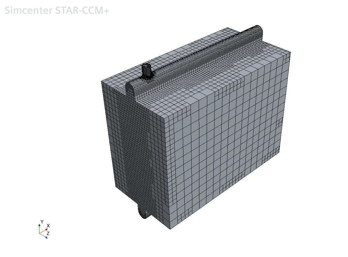
- Save the simulation.