Revolve and Revolve Cut Panels
Use the following properties to define the behavior of the revolve or revolve cut feature.
| Input Type | Specifies the type of input to revolve. | ||
| Sketch | Allows you to use a sketch profile to revolve. | ||
| Edges | Allows you to use edges to revolve. | ||
| Sketch/Edges to Revolve | Specifies a sketch or edges to revolve. | ||
| Body Type | Defines the type of body that results from the operation. | ||
| Solid | The resulting body is a closed solid. | ||
| Sheet | The resulting body is an open sheet body. | ||
| Direction | Specifies the direction of the revolution. | ||
| Normal | Revolves the sketch in the normal direction. | ||
| Reverse | Revolves the sketch opposite to the normal direction. | ||
| Revolve Options | Specifies whether the revolve extends in a single direction or both directions. | ||
| One Way | Revolves
the sketch in one direction (specified in the
Direction parameter).  |
||
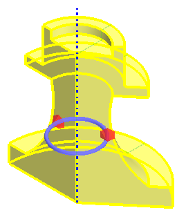
| Two Way Symmetric | Revolves
the sketch the same amount in both directions.  |
||
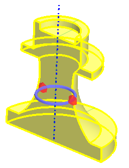
| Two Way Asymmetric | Revolves
the sketch in both directions. The revolve angle on either side of
the sketch can be different. This option activates the Asymmetric Angle parameter.  |
||
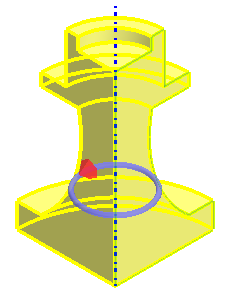
| Angle | Specifies the angle through which the sketch is revolved. You can define the angle using a constant value, design parameter, or the arrow in the 3D-CAD View scene. If you set the angle using a design parameter the arrow is hidden in the scene. | ||
| Asymmetric Angle | Specifies the asymmetric angle through which the sketch is revolved. This option is activated when you set Revolve Options to Two Way Asymmetric. | ||
| Axis Type | Specifies the axis of about which the sketch revolves. | ||
| Specified | Allows you to manually specify the axis of rotation direction and position. In the 3D-CAD View scene, you can click and drag the light blue arrow to change the orientation of the revolve. If you specify the rotation direction or position using a design parameter, the respective arrow or triad is hidden in the scene. | ||
| Axis Direction | Specifies the direction of the axis of revolution. Enter the [X, Y, Z] components of the direction vector. | ||
| Axis Position | Specifies the position of the axis of revolution. Enter the [X, Y, Z] coordinates for the axis or use the triad within the 3D-CAD View window. | ||
| Coordinate System | Defines the coordinate system for the axis of revolution. If you have specified an alternative coordinate system within the simulation, you can define the axis with reference to this coordinate system instead of the default, Laboratory. | ||
| Construction Line | Specifies a construction line as the axis of rotation. Select the construction line from the drop-down menu. If the selected sketch contains multiple construction lines, these are listed in the drop-down menu. | ||
| Reference Axis | Specifies a reference axis as the axis of rotation. Select an existing reference axis from the drop-down menu. See Working with Reference Geometry in 3D-CAD. | ||
| Body Interaction | Specifies how the solid body that is created by the revolve feature interacts with other bodies adjacent to it, as defined by Interacting Bodies. | ||
| None | The new body is added to the Bodies manager on its own. No change is made if the body is adjacent to, or overlaps, surrounding bodies. | ||
| Merge | The new body is united with any adjacent or overlapping bodies; otherwise it is added on its own to the Bodies manager. | ||
| Imprint | The edges of the revolved body are imprinted on any adjacent or overlapping bodies. Part contacts are created when the operation is executed. | ||
| Bodies to Interact | Specifies the bodies which interact with the feature. | ||
| All | The feature interacts with all contacting bodies. | ||
| Selected | The feature interacts with selected bodies only. Click inside the Interacting Bodies group box and select the bodies to interact with from the from the 3D-CAD View scene. These bodies are highlighted in blue. | ||
| Bodies to Cut | Specifies the bodies that the feature cuts. | ||
| All | The feature cuts all bodies. | ||
| Selected | The feature cuts only selected bodies. Click inside the Cut Bodies group box and select the bodies to cut from the 3D-CAD View scene. These bodies are highlighted in blue. | ||