Creating a Mass Flow Monitor Plot
You create a monitor plot for normalized mass flow through the outlet.
To create a monitor plot for normalized mass flow through the outlet:
- Right-click Reports and select .
- Rename the Mass Flow 1 report to Mass Flow.
- Select the Mass Flow node and set the Parts to .
-
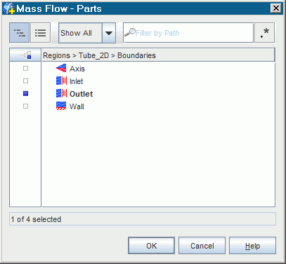
Select
Outlet from the dialog which appears when editing the
Parts property value.

- Right-click and select Create Monitor and Plot from Report.
- Select .
- Set Normalization Option to Manual.
- Make sure that the Trigger property is set to Time Step.
-
Expand the
node and select
.
The normalization factor is chosen as the mass outflow for the first iteration.
- Set Normalization Factor to 3.74E-5.
Edit the plot graphics settings.
- Rename to Normalized Mass Flow Monitor Plot.
-
Set the following properties:
Node Property Setting Normalized Mass Flow Monitor Plot Title Normalized Mass Flow Monitor Plot 
Minimum 0.0 Lock Minimum Deactivated
Maximum 20.0 Lock Maximum Activated
 Title
Title
Title Physical Time (s) 
Minimum 0.0 Lock Minimum Deactivated
Maximum 1.0 Lock Maximum Activated
 Title
Title
Title Mass Flow Monitor - Save the simulation.